Rockwell Automation 21G PowerFlex 750-Series AC Drives Programming Manual User Manual
Page 134
134
Rockwell Automation Publication 750-PM001J-EN-P - October 2014
Chapter 3
Drive Port 0 Parameters
POSITION C
O
N
TR
O
L
Po
si
ti
on
C
fg
/S
ts
722
Psn Selected Ref
Position Selected Reference
Indicates output of the position referencing. When the Spd/Torq/Pos mode P313 [Actv
SpTqPs Mode] is the position direct mode (Option 10), the value of the position direct
reference P767 [Psn Direct Ref] appears on this parameter. When the Spd/Torq/Pos
mode P313 [Actv SpTqPs Mode] is the position point-to-point mode (Option 7) or the
speed/position profiler mode (Option 6), the position point-to-point reference P776
[PTP Reference] appears on this parameter.
Default:
Min/Max:
0
–2147483648 / 2147483647
RO
32-bit
Integer
723
Psn Command
Position Command
Indicates final accumulated command to the position regulator. When the position
regulator is not active, this parameter is initialized to P836 [Psn Actual].
Default:
Min/Max:
0
–2147483648 / 2147483647
RO
32-bit
Integer
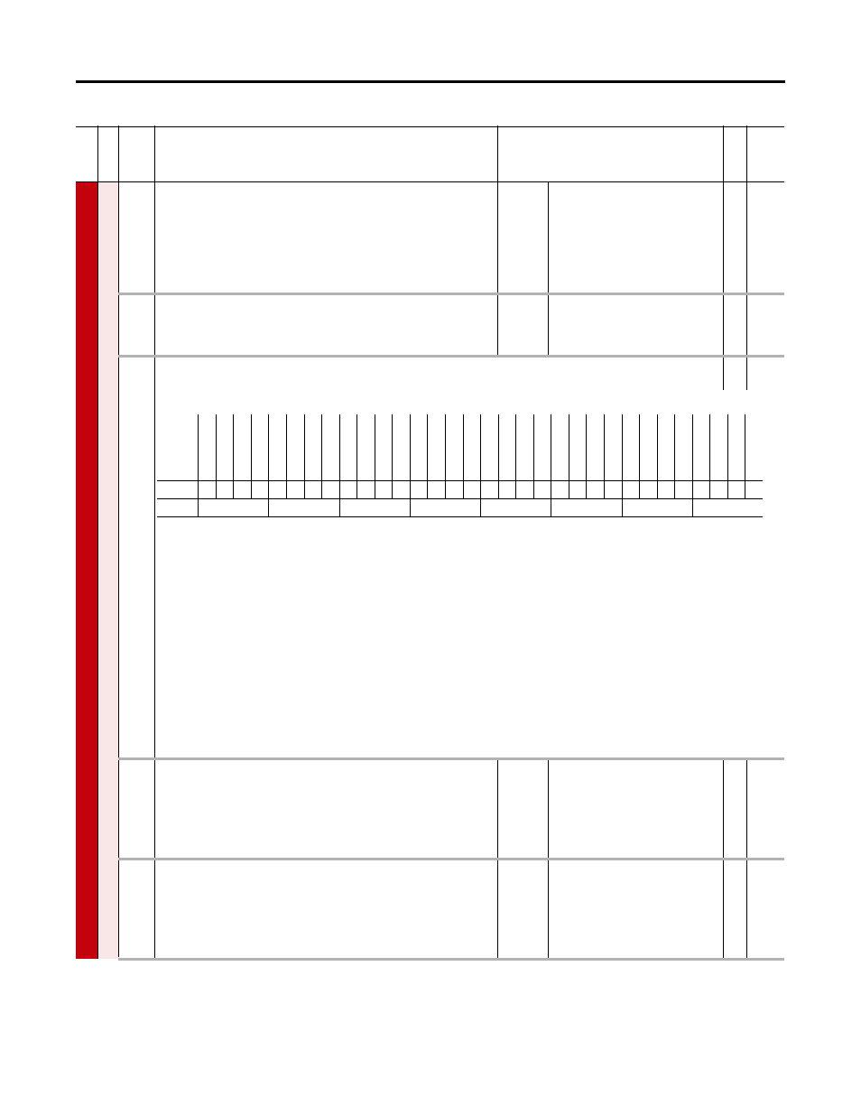
724
Psn Reg Status
Position Regulator Status
RO
32-bit
Integer
Indicates status of position control logic.
Bit 0 “OffsetIntgtr” – Indicates the position offset Integrator is active with the position offset integrator bit P721 [Position Control] Bit 3 “OffsetVel En” is on.
Bit 1 “Offset ReRef” – Indicates the position offset re-referencing is active with the position offset re-referencing bit P721 [Position Control] Bit 2 “Offset ReRef” is
on.
Bit 2 “Psn Intgrtr” – Indicates the position integrator is active with the position integrator bit P721 [Position Control] Bit 1 “Intgrtr En” is on.
Bit 3 “Integ Lmt Lo” – Indicates the position integrator is at the low limit.
Bit 4 “Integ Lmt Hi” – Indicates the position integrator is at the high limit.
Bit 5 “Spd Lmt Lo” – Indicates the position regulator output (speed) is at the low limit.
Bit 6 “Spd Lmt Hi” – Indicates the position regulator output (speed) is at the high limit.
Bit 7 “Psn Reg Actv” – Indicates the position regulator is active
Bit 8 “Intgrtr Hold” – Indicates the position Integrator is held in present state
Bit 9 “PsnW1Detect” – Indicates the position watch 1 has detected motor position equal to its setpoint, from the proper direction.
Bit 10 “PsnW2Detect” – Indicates the position watch 2 has detected motor position equal to its setpoint, from the proper direction.
Bit 11 “InPsn Detect” – Indicates P835 [Psn Error] is within the position band specified by the in-position band P726 [In Pos Psn Band]
725
Zero Position
Zero Position
Sets the absolute user zero position. When the zero position bit P721 [Position Control]
Bit 4 “Zero Psn” is set, P836 [Psn Actual] accumulates the value of P847 [Psn Fdbk] - the
P725 [Zero Position], and P836 [Psn Actual] becomes zero when P847 [Psn Fdbk] is at
the zero position. The homing function also sets the value after homing process is
completed.
Default:
Min/Max:
0
–2147483648 / 2147483647
RW 32-bit
Integer
726
In Pos Psn Band
In Positive Position Bandwidth
Sets the overall bandwidth of the in position detector. The detector sets the in-position
detect bit P724 [Psn Reg Status] Bit 11 “InPsn Detect” when P835 [Psn Error] is within
this position band for a sufficient time specified by the in-position dwell time P727 [In
Pos Psn Dwell]. A modest hysteresis count is added to the position bandwidth after the
position error is within specified limits.
Default:
Min/Max:
200
0 / 2147483647
RW 32-bit
Integer
Fi
le
Grou
p
No.
Display Name
Full Name
Description
Values
Re
ad
-W
ri
te
Da
ta
T
ype
Options
Re
ser
ve
d
Re
ser
ve
d
Re
ser
ve
d
Re
ser
ve
d
Re
ser
ve
d
Re
ser
ve
d
Re
ser
ve
d
Re
ser
ve
d
Re
ser
ve
d
Re
ser
ve
d
Re
ser
ve
d
Re
ser
ve
d
Re
ser
ve
d
Re
ser
ve
d
Re
ser
ve
d
Re
ser
ve
d
Re
ser
ve
d
Re
ser
ve
d
Re
ser
ve
d
Re
ser
ve
d
InP
sn
D
et
ec
t
Ps
nW
2D
et
ec
)
Ps
nW
1D
et
ec
t
(1
)
(1) 755 drives only.
Int
gr
tr
Hol
d
Ps
n R
eg
Ac
tv
Sp
d L
m
t H
i
Sp
d L
m
t L
o
In
te
g Lm
t Hi
In
te
g Lm
t L
o
Ps
n I
ntg
rt
r
O
ff
set Re
Ref
Of
fs
et
In
tg
tr
Default
0
0
0
0
0
0
0
0
0
0
0
0
0
0
0
0
0
0
0
0
1
0
0
0
0
0
0
0
0
0
0
0
Bit
31 30 29 28 27 26 25 24 23 22 21 20 19 18 17 16 15 14 13 12 11 10 9
8
7
6
5
4
3
2
1
0
0 = False
1 = True