Rockwell Automation 21G PowerFlex 750-Series AC Drives Programming Manual User Manual
Page 476
476
Rockwell Automation Publication 750-PM001J-EN-P - October 2014
Appendix B
Application Notes
Predictive Maintenance for Floor Mount Drives (Frames 8…10)
There can be multiple power structures in parallel on floor mount drives; and
therefore, multiple sets of fans, which make the predictive maintenance more
complicated than on wall mount drives.
To minimize the number of parameters, the parallel inverters, converters, and
precharge units do not have separate [Total Life] and [Remaining Life]
parameters. The user must calculate the individual [Remaining Life] values in the
controller.
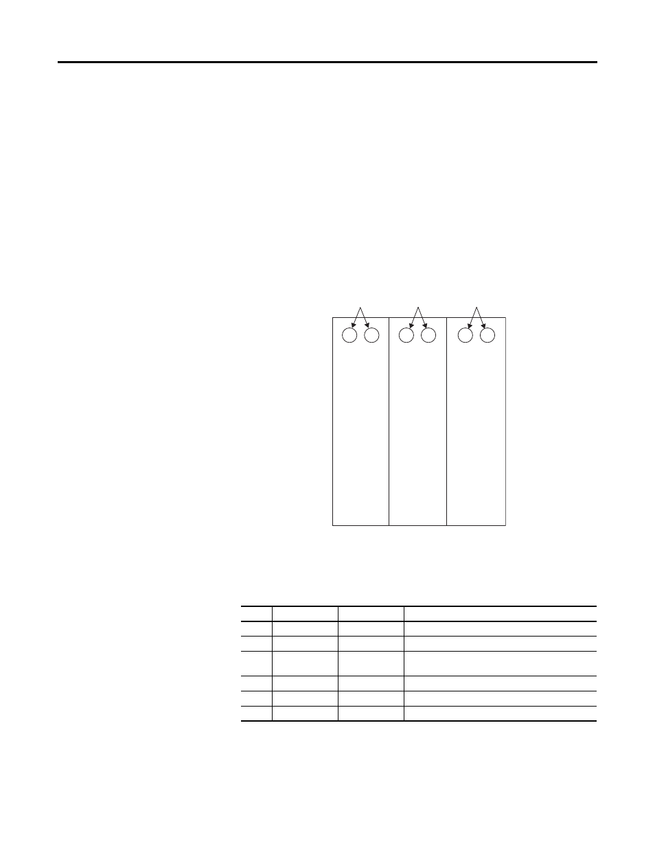
A frame 10 drive has three power structures, and three sets of cabinet fans,
heatsink fans, and internal stirring fans.
These parameters are available for the cabinet fans.
Table 3 - Cabinet Fan Parameters
The user must calculate the [Remaining Life] parameter values for the cabinet
fans in each power structure. This is needed anytime the [Elapsed Life] parameter
of one power structure differs from another. This difference can occur when one
power structure has been replaced or serviced separately from the others.
Node
Parameter No.
Parameter Name
Description
0
482
CBFan TotalLife
Displays the expected lifespan for a cabinet fan.
0
483
CBFan ElpsdLife
Displays the greatest expended life of a cabinet fan.
0
484
CBFan RemainLife
Displays the difference between P482 [CBFan TotalLife] and
P483 [CBFan ElpsdLife].
11
138
C1 CBFanElpsdLife
Displays the expended life of the fans on cabinet 1.
11
238
C2 CBFanElpsdLife
Displays the expended life of the fans on cabinet 2.
11
338
C3 CBFanElpsdLife
Displays the expended life of the fans on cabinet 3.
C1
Cabinet Fans
C2
Cabinet Fans
C3
Cabinet Fans
Power Structure
1
Power Structure
2
Power Structure
3