Rockwell Automation 21G PowerFlex 750-Series AC Drives Programming Manual User Manual
Page 206
206
Rockwell Automation Publication 750-PM001J-EN-P - October 2014
Chapter 3
Drive Port 0 Parameters
A
PPLI
CA
TION
S
Va
ri
ab
le
B
oo
st
1548
VB Current Rate
Variable Boost Current Rate
Output current rate of change.
Default:
Min/Max:
0.0
–/+1000.0
RO
Real
1549
VB Current Hyst
Variable Boost Current Hysteresis
Sets the hysteresis level around P1550 [VB Cur Thresh] for the variable boost voltage
function.
Default:
Min/Max:
0.0
–/+100.0
RW Real
1550
VB Cur Thresh
Variable Boost Current Threshold
Sets the P1548 [VB Current Rate] trigger level for the variable boost voltage function.
The trigger is not active until P1538 [VB Time] time has expired following a drive start.
P1535 [VB Config] Bit 2 “Rising Edge” = 0:
The value of [VB Current Rate] must first pass through [VB Cur Thresh] + P1549 [VB
Current Hyst] then [VB Cur Thresh] in order to cause a boost voltage trigger event.
P1535 [VB Config] Bit 2 “Rising Edge” = 1:
The value of P1548 [VB Current Rate] must first pass through [VB Cur Thresh] - P1549
[VB Current Hyst] then [VB Cur Thresh] in order to cause a boost voltage trigger event.
Default:
Min/Max:
–25.0
–/+1000.0
RW Real
1551
VB Rate Lag Freq
Variable Boost Rate Lag Frequency
Sets the lag (cutoff) frequency of the current magnitude low pass filter.
The output of this filter is displayed in P1548 [VB Current Rate].
Units:
Default:
Min/Max:
R/S
2.60
0.01 / 100.00
RW Real
Fi
le
Grou
p
No.
Display Name
Full Name
Description
Values
Re
ad
-W
ri
te
Da
ta
T
ype
1560
See
.
Fil
e
Gr
oup
No.
Display Name
Full Name
Description
Values
Read-W
rite
Da
ta
T
yp
e
APPLIC
AT
ION
S
Sp
in
dl
e O
ri
en
t
Important: After the Spindle Orient group is set up for an application, any subsequent
changes to parameter settings will require a drive reset for the changes to take affect.
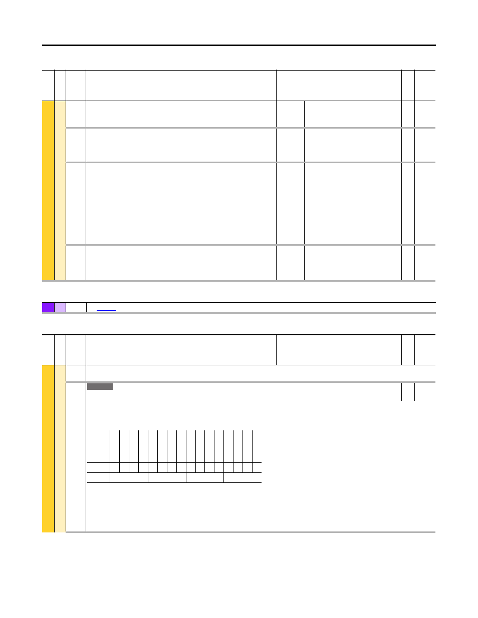
1580
SO Config
Spindle Orientation Configuration
RW 16-bit
Integer
Configures the options for the Spindle Orientation function.
Function requires P35 [Motor Ctrl Mode] is set to option 3 “Induction FV,” 6 “PM FV,” or 10 “IPM FV.” P125 [Pri Vel Fdbk Sel] and P135 [Psn Fdbk Sel] must also be set
up accordingly.
Bit 0 “Home DI” – Selects the type of Homing signal (Marker Pulse vs. Digital Input Switch). 1 = Home signal. 0 = Z Channel.
Bit 1 “Home DI Inv” – Rising/Falling Edge of Homing Input.
Bit 2 “Recap Hm Psnv” – Re-capture Home Position. Allows the drive to find Home after a power or drive reset. Typically set to 1 “Enabled.”
Bit 3 “ShortestPath” – Allow direction reversal to obtain shortest distance traveled.
Bit 4 “Scale Invert” – Inverts the calculation for the user-defined units value. This improves resolution as the value of P1587 [SO Cnts per Rvls] increases.
755
Options
Re
se
rv
ed
Re
se
rv
ed
Re
se
rv
ed
Re
se
rv
ed
Re
se
rv
ed
Re
se
rv
ed
Re
se
rv
ed
Re
se
rv
ed
Re
se
rv
ed
Re
se
rv
ed
Re
se
rv
ed
Sc
al
e I
nv
er
t
Shor
te
stP
at
h
Re
ca
p H
m
P
sn
Ho
me
DI In
v
Ho
me
DI
Default
0
0
0
0
0
0
0
0
0
0
0
0
0
0
0
0
Bit
15 14 13 12 11 10 9
8
7
6
5
4
3
2
1
0
0 = Disabled
1 = Enabled