Rockwell Automation 21G PowerFlex 750-Series AC Drives Programming Manual User Manual
Page 151
Rockwell Automation Publication 750-PM001J-EN-P - October 2014
151
Drive Port 0 Parameters
Chapter 3
Fil
e
Gr
ou
p
No.
Display Name
Full Name
Description
Values
Re
ad
-Write
Da
ta T
ype
CO
MMUNIC
AT
ION
D
P
I Da
tali
nks
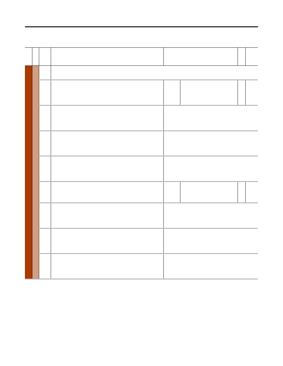
Important: DPI Datalinks parameters are used for datalinks on legacy 20-COMM-n
communication devices. For embedded EtherNet/IP or 20-750 option datalinks, refer to
the parameters associated with the specific option module.
895
896
Data In A1
Data In A2
Data Input An
Parameter number whose value will be written from a communications device data
table.
Default:
Min/Max:
0 (0 = “Disabled”)
0 / 159999
RW 32-bit
Integer
897
898
Data In B1
Data In B2
Data Input Bn
Parameter number whose value will be written from a communications device data
table.
See [Data In A1].
899
900
Data In C1
Data In C2
Data Input Cn
Parameter number whose value will be written from a communications device data
table.
See [Data In A1].
901
902
Data In D1
Data In D2
Data Input Dn
Parameter number whose value will be written from a communications device data
table.
See [Data In A1].
905
906
Data Out A1
Data Out A2
Data Output An
Parameter number whose value will be written to a communications device data table.
Default:
Min/Max:
0 (0 = “Disabled”)
0 / 159999
RW 32-bit
Integer
907
908
Data Out B1
Data Out B2
Data Output Bn
Parameter number whose value will be written from a communications device data
table.
See [Data Out A1].
909
910
Data Out C1
Data Out C2
Data Output Cn
Parameter number whose value will be written from a communications device data
table.
See [Data Out A1].
911
912
Data Out D1
Data Out D2
Data Output Dn
Parameter number whose value will be written from a communications device data
table.
See [Data Out A1].