Rockwell Automation 21G PowerFlex 750-Series AC Drives Programming Manual User Manual
Page 451
Rockwell Automation Publication 750-PM001J-EN-P - October 2014
451
Application Notes
Appendix B
3.
Set minimum speed.
4.
Set maximum speed limits.
5.
Set digital input functions.
Speed Select Inputs
Clear Fault Input
6.
Set speed reference.
Program preset speeds according to Speed Select inputs that are used.
7.
Run crane with crane control unit.
Verify speed references by checking P930 [Speed Ref Source].
8.
Set speed loop tuning.
P645 [Speed Reg Kp] = P636 [Speed Reg BW] x P76 [Total Inertia] = BW x J (Inertia)
Drive Parameter
Setting
P522 [Min Fwd Speed]
0.00
P523 [Min Rev Speed]
0.00
Drive Parameter
Setting
P520 [Max Fwd Speed]
Forward speed limit that is used during normal operation.
Not more than the motor nominal frequency.
P521 [Max Rev Speed]
Reverse speed limit that is used during normal operation.
Not more than the motor nominal frequency.
Drive Parameter
Setting
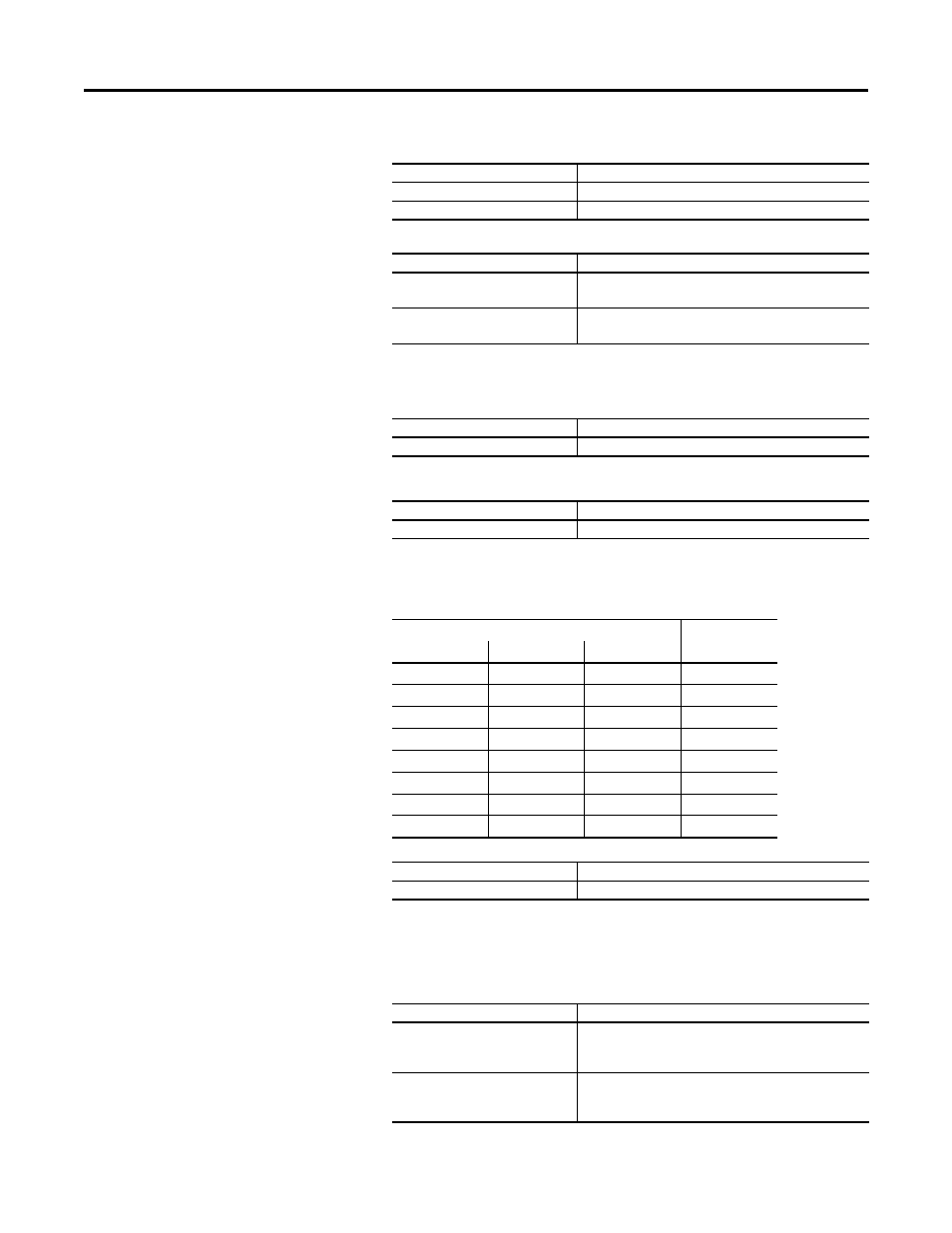
P173…175 [DI Speed Sel n]
I/O Port Number, P1 [Dig In Sts], Bit n
Drive Parameter
Setting
P156 [DI Clear Fault]
I/O Port Number, P1 [Dig In Sts], Bit n
Input Status (1 = Input Actuated)
Auto Reference
Source
DI Speed Sel 2
DI Speed Sel 1
DI Speed Sel 0
0
0
0
Reference A
0
0
1
Reference A
0
1
0
Reference B
0
1
1
Preset Speed 3
1
0
0
Preset Speed 4
1
0
1
Preset Speed 5
1
1
0
Preset Speed 6
1
1
1
Preset Speed 7
I/O Module Parameter (Port X)
Setting
P10 [RO0 Sel]
Port 0, P935 [Drive Status 1], Bit 16 “Running”
Drive Parameter
Setting
P636 [Speed Reg BW]
20 R/S
Defines the reactivity of the speed regulator. This parameter is
used to calculate Kp and Ki gains.
P76 [Total Inertia]
1.5 Secs
This value can be increased or decreased depending on Speed
regulator response.