Position control – phase locked loop, Figure 47 - position control - phase locked loop – Rockwell Automation 21G PowerFlex 750-Series AC Drives Programming Manual User Manual
Page 413
Rockwell Automation Publication 750-PM001J-EN-P - October 2014
413
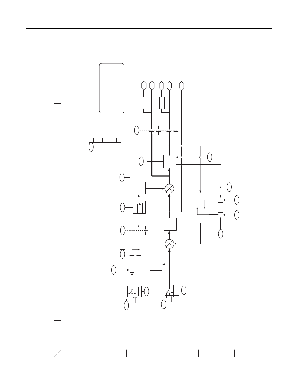
PowerFlex 755 Control Block Diagrams
Appendix A
Figure 47 - Position Control - Phase Locked Loop
1
2
3
4
5
6
B
A
D
C
F
E
H
G
I
Position Control –
Phase Locked Loop
LPF
Loop
Filter
X to V
Conv
0
0
VE
[ ]
[ ]
EGR
X
X
803
81
1
812
804
805
801
X
79
8
79
5
795
79
5
802
795
3
1
2
0
807
808
80
9
81
0
806
PLL BW
PLL Rvls Input
PLL EPR Input
PLL Rvls Output
PLL EPR
Output
PLL Virt Enc RPM
PLL LP
Filter BW
PL
L Con
tr
ol
PL
L Con
tr
ol
PLL Control
PL
L Ex
t Spd
S
ca
le
PLL Speed Out
PLL Speed OutAdv
PLL Enc Out
PLL Enc Out Adv
PLL Psn Out Fltr
+
+
+
-
PLL E
nable
0
1
0
1
Ext
Vel FF
Velo
city
FF
Accel
Comp
0
1
PL
L Con
tr
ol
79
5
0
PLL Control
1
PLL Ena
ble
Velocity
FF
2
Ext V
el FF
3
Accel C
omp
4
PCAM
Enable
5
PTP E
nable
6
Prof En
able
-
B
it4 enables PCAM function with PLL.
-
B
it5 ena
bles PTP function with
PLL
-
B
it6 ena
bles Pr
ofile
r function with PLL
Ca
n no
t select
multiple bits.
PL
L
refer
ences
mus
t connect to
appropriate outputs of the function.
0
0
1
PLL Ext
Spd Sel
79
6
79
7
Oth
er Re
f
Sources
PL
L Ext Spd
Stpt
Para
meter
Sel
ection
PLL Psn Ref Sel
799
800
Other Ref
Sour
ces
PL
L Psn Stp
t
P
aramete
r
S
election
[11F5]
[11F5]
[11F5]
[11F5]
Delay
Delay
PF
755 Rev
_10.a
Pag
e 14