Rockwell Automation 21G PowerFlex 750-Series AC Drives Programming Manual User Manual
Page 248
248
Rockwell Automation Publication 750-PM001J-EN-P - October 2014
Chapter 5
Embedded Feature and Option Module Parameters
11-S
eries I/
O
D
igi
tal O
utput
s
14
RO0 On Time
Relay Output 0 On Time
Sets the “ON Delay” time for the digital outputs. This is the time between the occurrence
of a condition and activation of the relay.
Units:
Default:
Min/Max:
Secs
0.0
0.0 / 600.0
RW Real
15
RO0 Off Time
Relay Output 0 Off Time
Sets the “OFF Delay” time for the digital outputs. This is the time between the
disappearance of a condition and de-activation of the relay.
Units:
Default:
Min/Max:
Secs
0.0
0.0 / 600.0
RW Real
20
RO1 Sel
Relay Output 1 Select – 11-Series I/O Module model 20-750-1132C-2R or 20-750-
1132D-2R is installed.
TO0 Sel
Transistor Output 0 Select – 11-Series I/O Module model 20-750-1133C-1R2T is
installed.
Selects the source that will energize the relay or transistor output.
Any status parameter bit can be used as an output source. For example P935 [Drive
Status 1] Bit 7 “Faulted.”
Default:
Min/Max:
0.00 (Disabled)
0.00 / 159999.15
RW 32-bit
Integer
21
RO1 Level Sel
Relay Output 1 Level Select – 11-Series I/O Module model 20-750-1132C-2R or 20-750-
1132D-2R is installed.
TO0 Level Sel
Transistor Output 0 Level Select – 11-Series I/O Module model 20-750-1133C-1R2T is
installed.
Selects the source of the level that will be compared.
Default:
Min/Max:
0 (Disabled)
0 / 159999
RW 32-bit
Integer
22
RO1 Level
Relay Output 1 Level – 11-Series I/O Module model 20-750-1132C-2R or 20-750-1132D-
2R is installed.
TO0 Level
Transistor Output 0 Level – 11-Series I/O Module model 20-750-1133C-1R2T is installed.
Sets the level compare value.
Default:
Min/Max:
0.0
–/+1000000.0
RW Real
23
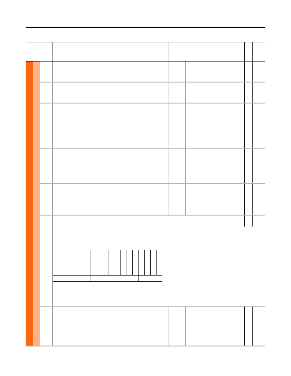
RO1 Level CmpSts
Relay Output 1 Level Compare Status – 11-Series I/O Module model 20-750-1132C-2R or 20-750-1132D-2R is installed.
RO
16-bit
Integer
TO0 Level CmpSts
Transistor Output 0 Level Compare Status – 11-Series I/O Module model 20-750-1133C-1R2T is installed.
Status of the level compare, and a possible source for a relay or transistor output. Relay Output n Select or Transistor Output n Select must have this selected to
energize the output. Can be used without a physical output as status information only.
Bit 0 “Less Than” – Level source is less than the level value.
Bit 1 “Grt Than Equ” – Level source is greater than or equal to the level value.
Bit 2 “Abs Less Than” – Absolute value of the level source is less than the absolute value of the level value.
Bit 3 “AbsGrtThanEq” – Absolute value of the level source is greater than or equal to the absolute value of the level value.
24
RO1 On Time
Relay Output 1 On Time – 11-Series I/O Module model 20-750-1132C-2R or 20-750-
1132D-2R is installed.
TO0 On Time
Transistor Output 0 On Time – 11-Series I/O Module model 20-750-1133C-1R2T is
installed.
Sets the “ON Delay” time for the digital outputs. This is the time between the occurrence
of a condition and activation of the relay or transistor.
Units:
Default:
Min/Max:
Secs
0.0
0.0 / 600.0
RW Real
Fi
le
Grou
p
No.
Display Name
Full Name
Description
Values
Re
ad
-W
ri
te
Da
ta
T
ype
Options
Re
ser
ved
Re
ser
ved
Re
ser
ved
Re
ser
ved
Re
ser
ved
Re
ser
ved
Re
ser
ved
Re
ser
ved
Re
ser
ved
Re
ser
ved
Re
ser
ved
Re
ser
ved
AbsG
rt
Th
anE
q
Abs L
ess
T
han
Gr
t Th
an
Eq
u
Le
ss T
han
Default
0
0
0
0
0
0
0
0
0
0
0
0
0
0
0
0
Bit
15 14 13 12 11 10 9
8
7
6
5
4
3
2
1
0
0 = Condition False
1 = Condition True