Rockwell Automation 21G PowerFlex 750-Series AC Drives Programming Manual User Manual
Page 339
Rockwell Automation Publication 750-PM001J-EN-P - October 2014
339
Troubleshooting
Chapter 6
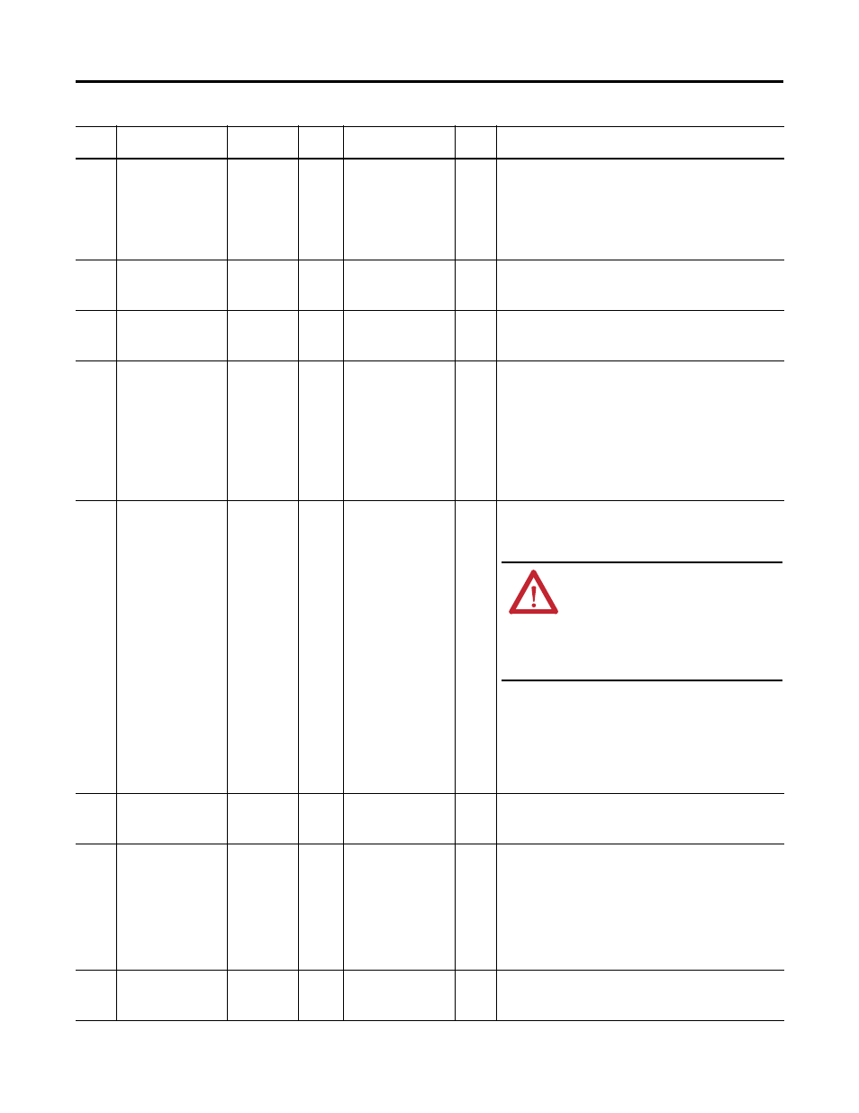
11138
11238
11338
P1 Brd Overtemp
P2 Brd Overtemp
P3 Brd Overtemp
Resettable
Fault
Coast
Y
The gate firing board is over temperature. This fault occurs when the
gate firing board temperature exceeds 70 °C.
• Check the cabinet fan wiring harness for loose connections or
damage and that the fan is running. If necessary, replace the fan
wiring harness and/or fan.
• Lower the ambient temperature.
• Replace the converter gate firing board.
11139
11239
11339
P1 Brd NTC Open
P2 Brd NTC Open
P3 Brd NTC Open
Non-Reset
Fault
Coast
The converter gate firing board NTC is open. An open NTC is assumed
when the temperature is below -40 °C.
• Replace the converter gate firing board.
11140
11240
11340
P1 Brd NTC Short
P2 Brd NTC Short
P3 Brd NTC Short
Non-Reset
Fault
Coast
The converter gate firing board NTC is shorted. A shorted NTC is assumed
when the temperature is above 200 °C.
• Replace the converter gate firing board.
11141
11241
11341
P1 Power Supply
P2 Power Supply
P3 Power Supply
Resettable
Fault
Coast
A power supply input voltage (24V input and/or +/-12V internal supply)
is operating outside of the acceptable range.
• Check input power to the converter gate firing board. The following
thresholds are used:
+24V is below 20.1V
+12V is below 10.0V
+12V is above 15.0V
-12V is above -10.0V
• If the power supply voltage is within the acceptable range, replace
the converter gate firing board.
11142
11242
11342
P1 Comm Loss
P2 Comm Loss
P3 Comm Loss
Resettable
Fault
Coast
The converter gate firing board lost communications (through the
power layer interface board) to the main control board. Once the root
cause of the communication fault has been resolved, power must be
cycled or a drive reset must be initiated to clear this fault.
• Verify that the fiber optic cables are properly connected to the
transceivers.
• Verify that the transceivers are properly seated in the ports.
• Verify that the fiber optic cable is not cracked or broken.
• Verify that power is applied to the fiber optic interface board, gate
firing board, and power layer interface board. If necessary, replace
the fiber optic interface, gate firing board, and/or power layer
interface board.
11143
11243
11343
P1 Firmware Flt
P2 Firmware Flt
P3 Firmware Flt
Non-Reset
Fault
Coast
A firmware fault has occurred.
• Reset the drive. If this fault persists, replace the converter gate firing
board.
11145
11245
11345
P1 DC Bus Short
P2 DC Bus Short
P3 DC Bus Short
Non-Reset
Fault
Coast
The peak current has exceeded 150% of the converter rating during the
precharge sequence. Peak charging current is normally limited to 50%
of the converter rating.
• Check for a DC bus short, internally and externally.
• Verify that the wiring harness to P10 on the converter gate firing
board is connected and not damaged. Replace the harness as
necessary.
• Verify that the capacitor bank is properly installed and connected.
• Check for an IGBT short and replace as necessary.
11157
11257
11357
P1 BFuse Harness
P2 BFuse Harness
P3 BFuse Harness
Non-Reset
Fault
Coast
A bus fuse wiring harness connection loss has been detected.
• Check the bus fuse harness and replace if necessary.
• If this problem persists, replace the converter gate firing board.
Event
No.
Fault/Alarm Text
Type
Fault
Action
Configuration
Parameter
Auto
Reset
Description/Action(s)
ATTENTION: Hazard of permanent eye damage
exists when using optical transmission
equipment. This product emits intense light and
invisible radiation. Do not look into fiber-optic
ports or fiber-optic cable connectors. Remove
power from the drive before disconnecting fiber
optic cables.