Diagram conventions and definitions – Rockwell Automation 21G PowerFlex 750-Series AC Drives Programming Manual User Manual
Page 364
364
Rockwell Automation Publication 750-PM001J-EN-P - October 2014
Appendix A
PowerFlex 753 Control Block Diagrams
Diagram Conventions and
Definitions
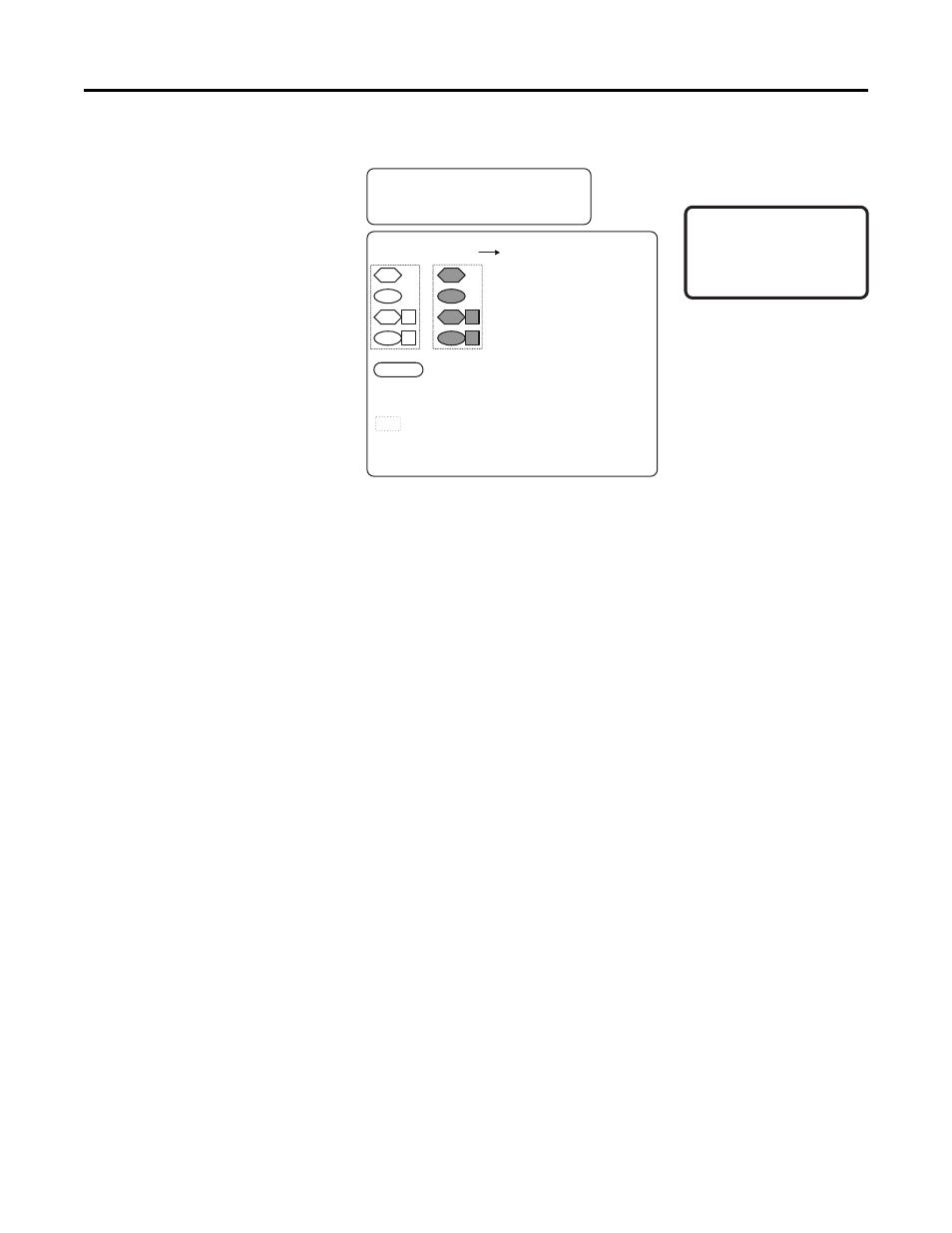
Definitions of the Per Unit system:
1.0 PU Position = Distance traveled / 1sec at Base Spd
1.0 PU Speed = Base Speed of the Motor
1.0 PU Torque = Base Torque of the Motor
Read Only Parameter with Bit Enumeration
Read / Write Parameter with Bit Enumeration
Provides additional information
Read Only Parameter
Read / Write Parameter
Symbol Legend:
* Notes, Important:
(1) These diagrams are for reference only and may
not accurately reflect all logical control signals;
actual functionality is implied by the approximated
diagrams. Accuracy of these diagrams is not
guaranteed.
Drive
Parameters
Option Module
Parameters
Requires port number.
( ) = Enumerated Parameter
[ ] = Page and Coordinate
ex. 3A2 = pg 3, Column A, Row 2
= Constant value
‘d’
= Prefix refers to Diagnostic Item Number
ex. d33 = Diagnostic Item 33