Rockwell Automation 21G PowerFlex 750-Series AC Drives Programming Manual User Manual
Page 286
286
Rockwell Automation Publication 750-PM001J-EN-P - October 2014
Chapter 5
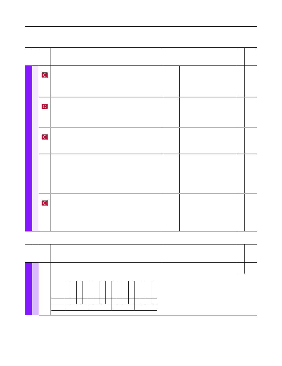
Embedded Feature and Option Module Parameters
Fil
e
Gr
ou
p
No.
Display Name
Full Name
Description
Values
Re
ad
-Write
Da
ta T
ype
Un
iv
ersal F
eedb
ack
Encoder O
u
t
80
Enc Out Sel
Encoder Output Select
Selects the Encoder Output. If the feedback 0 or 1 device is configured as A Quad B Z then
this parameter has to be set to None. Otherwise, there is an Encoder Output Alarm (Bit
16 of [Module Sts]).
Default:
Options:
0 = “None”
0 = “None”
1 = “Reserved”
2 = “Sine Cosine”
3 = “Channel X” (FB0 Channel)
4 = “Channel Y” (FB1 Channel)
RW 32-bit
Integer
81
Enc Out Mode
Encoder Output Mode
Configures the Encoder Output type.
“A Quad B” (0) – Sets the phase relationship between the A and B signal.
“Inv A Quad B” (1) – Inverts the phase relationship between the A and B signal. Forward
and reverse exchange meanings.
Default:
Options:
0 = “A Quad B”
0 = “A Quad B”
1 = “Inv A Quad B”
RW 32-bit
Integer
82
Enc Out FD PPR
Full Digital Encoder Feedback Emulator Output Pulses Per Revolution
Specifies the emulated encoder output PPR when the Feedback Selection (FB device 0/1
Sel) is set to Full Digital (values 5…10). When the Feedback selection is set to Sin/Cos
“SC”, the Sin/Cos native PPR defines the emulated encoder outputs PPR.
Default:
Options:
1 = “1024 PPR”
0 = “512 PPR”
1 = “1024 PPR”
2 = “2048 PPR”
3 = “4096 PPR”
RW 32-bit
Integer
83
Enc Out Z Offset
Encoder Output Z Offset
Configures the offset of the Z pulse for both simulated and emulated encoder output.
The marker offset is specified within one revolution.
Simulated mode is used for full digital rotary devices and is selected by “Channel X” and
“Channel Y” in P80 [Enc Out Sel].
Emulated mode is used when “Sine Cosine” devices are selected in P80 [Enc Out Sel].
The encoder output function cannot be used with linear feedback devices.
Units:
Default:
Min/Max:
PPR
0
0 / 100000
RW 32-bit
Integer
84
Enc Out Z PPR
Encoder Output Z Pulses Per Revolution
Configures the number of Z-Pulses per encoder revolution.
For example, if “32 Z-Pulses” (5) is selected, then 32 Z pulses will be generated for each
complete revolution of the full digital input encoder. Each input encoder revolution will
produce the number of output pulses specified on the A and B output channels in
addition to 32 pulses on the Z output channel. The Z pulses will be evenly spaced
throughout the specified number of A/B output pulses.
Default:
Options:
0 = “1 Z-Pulse”
0 = “1 Z-Pulse”
1 = “2 Z-Pulses”
2 = “4 Z-Pulses”
3 = “8 Z-Pulses”
4 = “16 Z-Pulses”
5 = “32 Z-Pulses”
RW 32-bit
Integer
Fi
le
Grou
p
No.
Display Name
Full Name
Description
Values
Read-W
ri
te
Da
ta
T
ype
Un
iv
ersal F
eedb
ack
R
egi
stra
ti
on
90
Rgsn Arm
Registration Arm
RW 16-bit
Integer
Selects Registration Latches to be used.
Options
Re
ser
ved
Re
ser
ved
Re
ser
ved
Re
ser
ved
Re
ser
ved
Re
ser
ved
Arm Latch
1
0
Arm Latch
9
Arm Latch
8
Arm Latch
7
Arm Latch
6
Arm Latch
5
Arm Latch
4
Arm Latch
3
Arm Latch
2
Arm Latch
1
Default
0
0
0
0
0
0
0
0
0
0
0
0
0
0
0
0
Bit
15 14 13 12 11 10 9
8
7
6
5
4
3
2
1
0
0 = Condition False
1 = Condition True