Rockwell Automation 21G PowerFlex 750-Series AC Drives Programming Manual User Manual
Page 272
272
Rockwell Automation Publication 750-PM001J-EN-P - October 2014
Chapter 5
Embedded Feature and Option Module Parameters
D
u
al
In
cr
em
en
ta
l En
co
de
r
Encoder 1
15
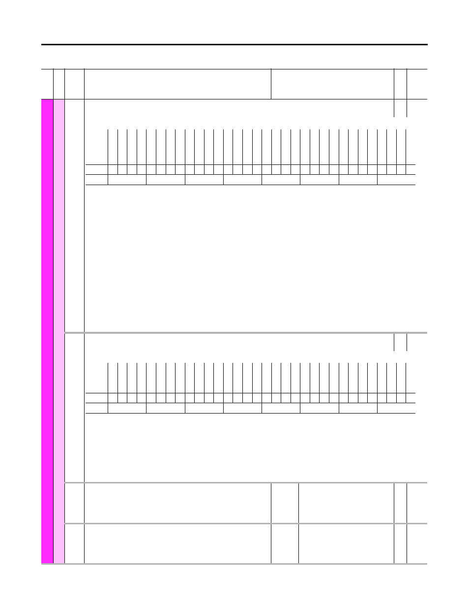
Enc 1 Sts
Encoder 1 Status
RW 32-bit
Integer
Status information for Encoder 1.
Bit 0 “Z Chan Enbl” – State of the corresponding bit in the [Enc 1 Cfg] parameter.
Bit 1 “A Chan Only” – State of the corresponding bit in the [Enc 1 Cfg] parameter.
Bit 2 “A Input” – State of encoder A input signal.
Bit 3 “A Not Input” – State of encoder A Not input signal.
Bit 4 “B Input” – State of encoder B input signal.
Bit 5 “B Not Input” – State of encoder B Not input signal.
Bit 6 “Z Input” – State of encoder Z input signal.
Bit 7 “Z Not Input” – State of encoder Z Not input signal.
Bit 8 “Marker Event” – When channel Z (marker pulse) is used, indicates that a marker pulse is detected. Automatically cleared in the homing routine or due to
clearing of encoder faults.
Bit 9 “Inv Home In” – State of the corresponding bit in the [Enc 1 Cfg] parameter. When set, the home input signal will be inverted.
Bit 10 “Home Input” – Active state of the Home Input signal. This status bit gets inverted if the “Inv Home In” bit is enabled.
Bit 11 “HomeIn Armed” – Indicates that the homing logic is configured to latch the encoder position upon the next transition of the home input.
Bit 12 “HomeIn Event” – Indicates that the homing logic has latched the encoder position in response to a transition of the home input.
Bit 13 “HomMrk Armed” – Indicates that the homing logic is configured to latch the encoder position upon the next marker (Z channel) pulse.
Bit 14 “HomMrk Event” – Indicates that the homing logic has latched the encoder position in response to a marker (Z channel) pulse.
Bit 15 “Direction” – State of the corresponding bit in the [Enc 1 Cfg] parameter.
16
Enc 1 Error Sts
Encoder 1 Error Status
RO
32-bit
Integer
Status information that will result in a feedback loss condition for Encoder 1.
Bit 0 “Open Wire” – Indicates that an input signal (A, B or Z) is in the same state as its complement (A Not, B Not, Z Not).
For open wire detection to work, the encoder signals must be differential (not single ended).
The Z channel is only checked when enabled.
Bit 1 “Phase Loss” – Indicates that more than 30 phase loss (open wire) events have occurred over an 8msec time period. The same restrictions apply as on [Enc 1
Cfg] Bit 0 “Z Chan Enbl.”
Bit 2 “Quad Loss” – Quadrature loss events occur when simultaneous edge transitions occur on both the A and B encoder channels. Indicates that more than 10
quad loss events over a 10 msec time period are detected. Only valid when both A and B channels are used (not “A Chan Only” in [Enc 1 Cfg]).
Bit 15 “SI Comm Loss” – Indicates a communication loss between the main control board and the encoder module over the Serial Interface backplane.
17
Enc 1 PhsLss Cnt
Encoder 1 Phase Loss Count
Displays the active value of the encoder module's Encoder 1 phase loss counter
hardware register. Values in this register accumulated over 8 msec are used to detect
Phase Loss errors.
Default:
Min/Max:
0
0 / 127
RO
32-bit
Integer
18
Enc 1 QuadLssCnt
Encoder 1 Quad Loss Count
Displays the active value of the encoder module's Encoder 1 quad loss counter hardware
register. Values in this register accumulated over 8 msec are used to detect Quad Loss
errors.
Default:
Min/Max:
0
0 / 15
RO
32-bit
Integer
Fi
le
Grou
p
No.
Display Name
Full Name
Description
Values
Re
ad
-W
ri
te
Da
ta
T
ype
Options
Res
er
ve
d
Res
er
ve
d
Res
er
ve
d
Res
er
ve
d
Res
er
ve
d
Res
er
ve
d
Res
er
ve
d
Res
er
ve
d
Res
er
ve
d
Res
er
ve
d
Res
er
ve
d
Res
er
ve
d
Res
er
ve
d
Res
er
ve
d
Res
er
ve
d
Res
er
ve
d
Dir
ec
tion
HomMrk E
vent
HomMrk A
rme
d
HomeIn E
vent
HomeIn Armed
Home Input
In
v Hom
e In
Ma
rk
er E
vent
Z Not
In
pu
t
Z In
put
B N
ot In
put
B Input
A Not
Input
A Inpu
t
A Chan O
nly
Z Ch
an
En
bl
Default
0
0
0
0
0
0
0
0
0
0
0
0
0
0
0
0
0
0
0
0
0
0
0
0
0
0
0
0
0
0
0
0
Bit
31 30 29 28 27 26 25 24 23 22 21 20 19 18 17 16 15 14 13 12 11 10 9
8
7
6
5
4
3
2
1
0
Options
Re
se
rv
ed
Re
se
rv
ed
Re
se
rv
ed
Re
se
rv
ed
Re
se
rv
ed
Re
se
rv
ed
Re
se
rv
ed
Re
se
rv
ed
Re
se
rv
ed
Re
se
rv
ed
Re
se
rv
ed
Re
se
rv
ed
Re
se
rv
ed
Re
se
rv
ed
Re
se
rv
ed
Re
se
rv
ed
SI C
omm L
oss
Re
se
rv
ed
Re
se
rv
ed
Re
se
rv
ed
Re
se
rv
ed
Re
se
rv
ed
Re
se
rv
ed
Re
se
rv
ed
Re
se
rv
ed
Re
se
rv
ed
Re
se
rv
ed
Re
se
rv
ed
Re
se
rv
ed
Qu
ad
L
oss
Phase L
oss
Op
en
W
ire
Default
0
0
0
0
0
0
0
0
0
0
0
0
0
0
0
0
0
0
0
0
0
0
0
0
0
0
0
0
0
0
0
0
Bit
31 30 29 28 27 26 25 24 23 22 21 20 19 18 17 16 15 14 13 12 11 10 9
8
7
6
5
4
3
2
1
0