Position control - spindle orientation, Figure 52 - position control - spindle orientation – Rockwell Automation 21G PowerFlex 750-Series AC Drives Programming Manual User Manual
Page 418
418
Rockwell Automation Publication 750-PM001J-EN-P - October 2014
Appendix A
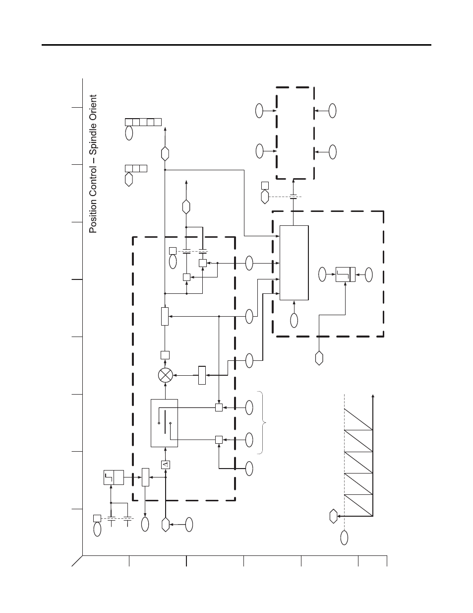
PowerFlex 755 Control Block Diagrams
Figure 52 - Position Control - Spindle Orientation
[ ]
[ ]
EGR
1
2
3
4
5
6
B
A
D
C
F
E
H
G
I
X
X
Pos Fdbk Sel
13
5
15
83
ReC
ap
Σ
Mod
0
1
At SO
Speed
Mode
1581
+
-
1589
1590
158
3
SO Offset
SO
Offset
Modu
lo Divi
der
SO Position Out
SO
U
nit
Ou
t
158
4
SO EPR
Input
15
85
SO Rvls Input
15
86
SO Rvls Ou
tp
ut
1587
SO Cnts per Rvls
SO Status
15
88
SO Unit Scale
15
89
SO Position Out
15
87
SO Cnts
per Rvls
Psn Fdbk
Gear Ratio
84
7
0
X
*1
*1
*1: Product need to be with
in 32-
bits integer range
Position Feedback Input
2
O
rient C
plt
0
1
Hom
e DI
Hom
e DI In
v
SO Config
2
Recap
Hm P
sn
15
80
3
S
hortestP
ath
4
Sc
ale Inve
rt
Spindle Position Indicator
Ramped Spd Ref
59
4
Spindle Position Command
Spindle Position Planner
158
2
SO Setpoint
1591
SO Accel Time
15
92
SO Decel
Time
15
93
SO Fwd Vel Lmt
S
O
Re
v Ve
l L
m
t
15
94
SO Status
1581
1
Limit
1593
SO Fwd V
e
l Lmt
SO R
ev Vel Lmt
1594
M
ode
1580
4
Scale I
nvert
SO Config
0
1
÷
Re
Cap
Marker Pulse
Ho
me
D
I
Rising
Edge
0
Ho
m
e DI
SO Config
15
80
1
0
PF
755 Rev
_10.a
Pag
e 19