Inverter overload it, Figure 32 - inverter overload it – Rockwell Automation 21G PowerFlex 750-Series AC Drives Programming Manual User Manual
Page 396
396
Rockwell Automation Publication 750-PM001J-EN-P - October 2014
Appendix A
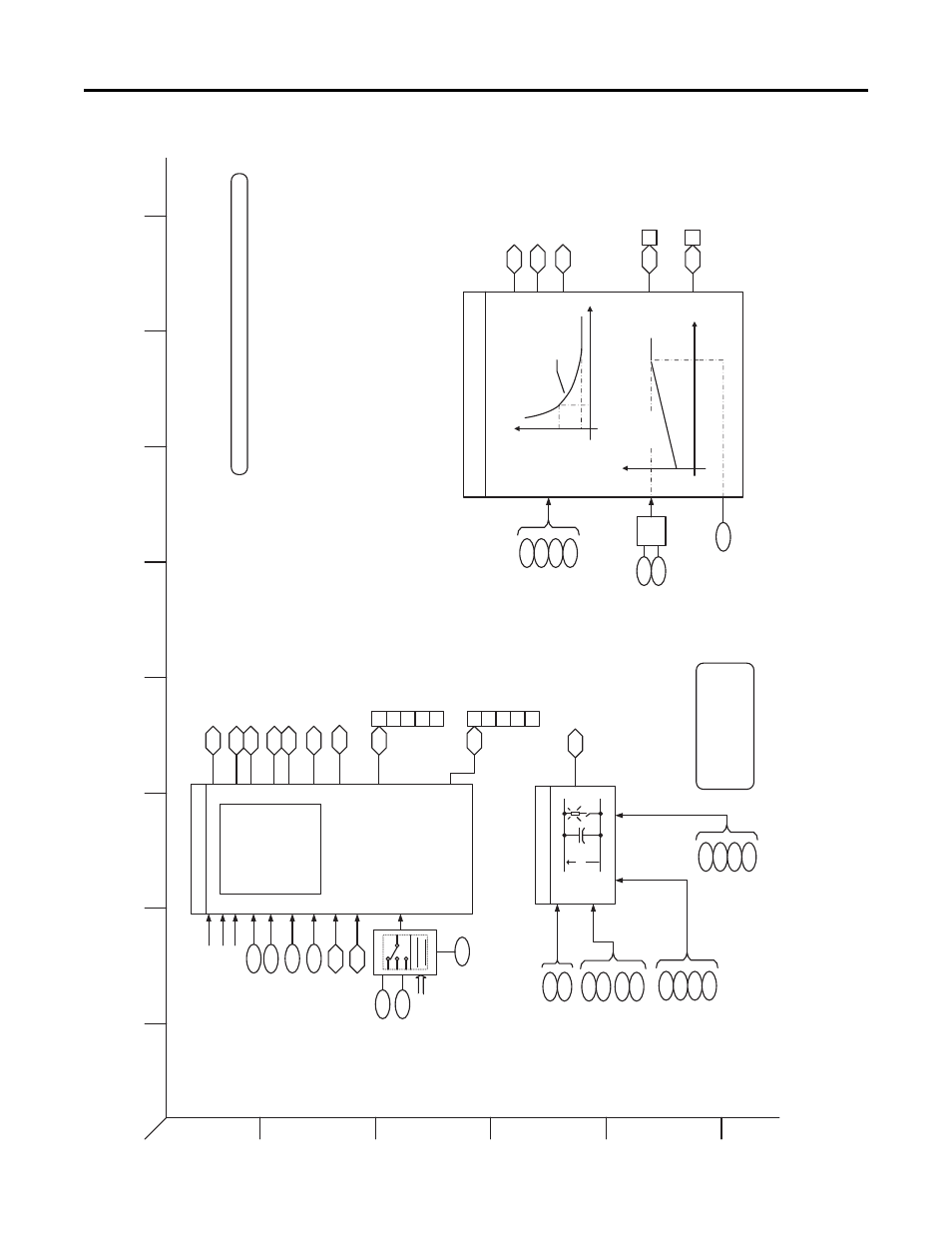
PowerFlex 753 Control Block Diagrams
Figure 32 - Inverter Overload IT
1
2
3
4
5
6
B
A
D
C
F
E
H
G
I
Inverter Overload IT
DB resistor
dc
bus
Bus Reg Mode A
Bus Reg Mode B
37
2
37
3
Bus Reg Lvl Cnfg
37
4
Bus R
eg
Le
vel
37
5
Bu
s Re
g Ki
38
0
Bus Reg Kp
38
1
Bus Limit Kp
376
Bus Limit Kd
377
Bus
Limit ACR Ki
378
Bus Limi
t ACR Kp
379
DB Resistor
Type
38
2
DB Ext Ohms
38
3
DB Ext Watts
38
4
DB Ex
tPulseWa
tts
38
5
*
No
te
: Para
me
te
rs
a
re
not functional when any
of the FV
motor control
mod
es
a
re
se
le
ct
ed
12
DC Bus Memory
Heatsink and
Junction Degree
Calculator
Inverter Overload (IT)
NTC
Pw
r EE Da
ta
Output Current
7
DC Bus Vol
tage
PW
M Fre
que
ncy
Pow
er Device
Characteristics
38
11
Drive OL Mode
42
0
Current Limit
Sel
42
1
42
2
423
Other Ref Sources
Cur
ren
t Limit 1
Current Limit 2
94
0
Drive OL Count
941
IGBT Temp Pct
94
2
IGBT Temp C
943
D
riv
e
Temp Pct
944
D
rive Temp C
424
A
ctive Cur Lmt
Alarm Status B
IGBT
OT
960
0
1
4
5
6
Heat
sink OT
Driv
e OL
CurL
mt Red
uc
PW
MFrq R
educ
Fault Status B
Driv
e OL
95
3
2
3
4
5
6
Heat
sink OT
Tran
sistor O
T
SinkU
nderT
m
p
Exce
ss Load
Mtr Over Load (I
2
T)
60 (Hot)
Motor
Current
Mo
to
r
Cur
rent
right of curve
1.
0 -
2.0
(1.
025 T
yp)
time (sec)
Motor
Spe
ed (H
z)
414
Mt
r OL
He
rt
z
X
26
Motor NP Amps
180
(
C
o
ld
)
102%
150%
41
3
Motor OL Factor
41
6
MtrOL Reset Time
50
%
Mtr OL
Ac
tv
410
Mtr OL
a
t Pwr Up
411
Mtr OL Alarm Lvl
412
Mtr OL Reset Lvl
415
418
Mtr OL Counts
419
Motor OL Trip Time
Alarm
Status A
M
otor OL
95
9
2
Fault Status A
95
2
2
Motor O
L
*
Param
eter
Select
ion
[18a G5], [18b G5]
d14
A
ctive PWM Freq
‘d’ Prefix Refer
s to Diagnostic Item Nu
mber (ex. d33) –
R
eference Symbol Legend
PF753
Rev_10.
a
Page 3
0
Duty Cycl
e
/ Rating
306
Vo
lta
ge Cla
ss
305