Rockwell Automation 21G PowerFlex 750-Series AC Drives Programming Manual User Manual
Page 186
186
Rockwell Automation Publication 750-PM001J-EN-P - October 2014
Chapter 3
Drive Port 0 Parameters
Fil
e
Gr
ou
p
No.
Display Name
Full Name
Description
Values
Re
ad
-Write
Da
ta T
ype
AP
PLIC
AT
IONS
P
ro
fil
in
g
1210
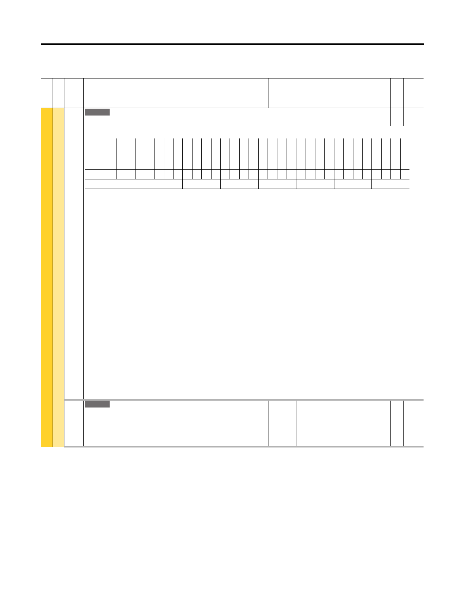
Profile Status
Profile Status
RO
32-bit
Integer
Indicates status of speed profile/position indexer control logic.
Bit 0 “Step Bit 0” – Bit 0 through Bit 4 indicate executing step number in the move table in binary format.
Bit 1 “Step Bit 1”
Bit 2 “Step Bit 2”
Bit 3 “Step Bit 3”
Bit 4 “Step Bit 4”
Bit 8 “Enabled” – Indicates that the profile control logic is enabled. When the drive is started with the profiler selection (Option 6) in the speed/torque/position
mode P313 [Actv SpTqPs Mode], this bit turns on.
Bit 9 “Running” – Indicates that the profile control logic is in running state.
Bit 10 “PositionMode” – Indicates that the profile control logic is using position control logic.
Bit 11 “Dwell” – Indicates that the profile control logic is in dwell state.
Bit 12 “Holding” – Indicates that the profile control logic is in holding states
Bit 13 “In Position” – Indicates that the target position has been reached at the completion of a move. The in position bandwidth P726 [In Pos Psn Band] can be
adjusted to affect when this bit is set with respect to the target position. This bit will be cleared when a new move is begun. The status of this bit is not meaningful
when using blended steps.
Bit 14 “Complete” – Indicates that all steps in the move table have been executed and a step with a End action has been reached. The profile control logic is
complete. This bit will be cleared when the profile is first enabled.
Bit 15 “Stopped” – Indicates that the profile control logic stops the drive following Bit 14 “Complete” and any additional dwell time specified for the End step. This
bit will be cleared when a new profile is begun.
Bit 16 “Resume” – Indicates that an existing step is to resume execution when the profile is enabled. A previously running step will then be allowed to complete.
When the bit is clear, the profile will begin at its Starting Step.
Bit 17 “Restart Step” – Follows the state of the restart step bit in P1213 [Profile Command] Bit 10 “Restart Step.”
Bit 18 “Vel Override” – Follows the state of the velocity override bit in P1213 [Profile Command] Bit 9 “Vel Override.”
Bit 19 “Home Not Set” – Indicates that the home position is not defined and the move table contains a position absolute move type. When this bit is set the profile
will not be allowed to execute. This bit will be cleared when either a homing function or position redefine function is completed.
1212
Units Traveled
Units Traveled
Indicates total number of units traveled. The relationship between the feedback edge
counts and the position units is determined by the P1215 [Counts Per Unit]. Actual
motor position is converted from the edge counts to this value using the P1215 [Counts
Per Unit].
Units:
Default:
Min/Max:
Cnts
Read Only
–/+ 2200000000.00
RO
Real
755
Options
Re
se
rv
ed
Re
se
rv
ed
Re
se
rv
ed
Re
se
rv
ed
Re
se
rv
ed
Re
se
rv
ed
Re
se
rv
ed
Re
se
rv
ed
Re
se
rv
ed
Re
se
rv
ed
Re
se
rv
ed
Re
se
rv
ed
Ho
me
No
t S
et
Ve
l O
verride
Re
st
ar
t S
te
p
Re
su
me
St
op
ped
Co
m
pl
ete
In P
osition
Ho
ldi
ng
Dw
el
l
Po
si
tio
nMo
de
Ru
nni
ng
Enabled
Re
se
rv
ed
Re
se
rv
ed
Re
se
rv
ed
St
ep Bit 4
St
ep Bit 3
St
ep Bit 2
St
ep Bit 1
St
ep Bit 0
Default
0
0
0
0
0
0
0
0
0
0
0
0
0
0
0
0
0
0
0
0
0
0
0
0
0
0
0
0
0
0
0
0
Bit
31 30 29 28 27 26 25 24 23 22 21 20 19 18 17 16 15 14 13 12 11 10 9
8
7
6
5
4
3
2
1
0
0 = Condition False
1 = Condition True
755