Rockwell Automation 21G PowerFlex 750-Series AC Drives Programming Manual User Manual
Page 328
328
Rockwell Automation Publication 750-PM001J-EN-P - October 2014
Chapter 6
Troubleshooting
Inverter (Port 10) Faults and
Alarms (Frame 8 and Larger)
The table below contains a list of Inverter-specific faults and alarms, the type of
fault or alarm, the action taken when the drive faults, the parameter used to
configure the fault or alarm (if applicable), and a description and action (where
applicable). These faults and alarms only apply to Frame 8 drives and larger.
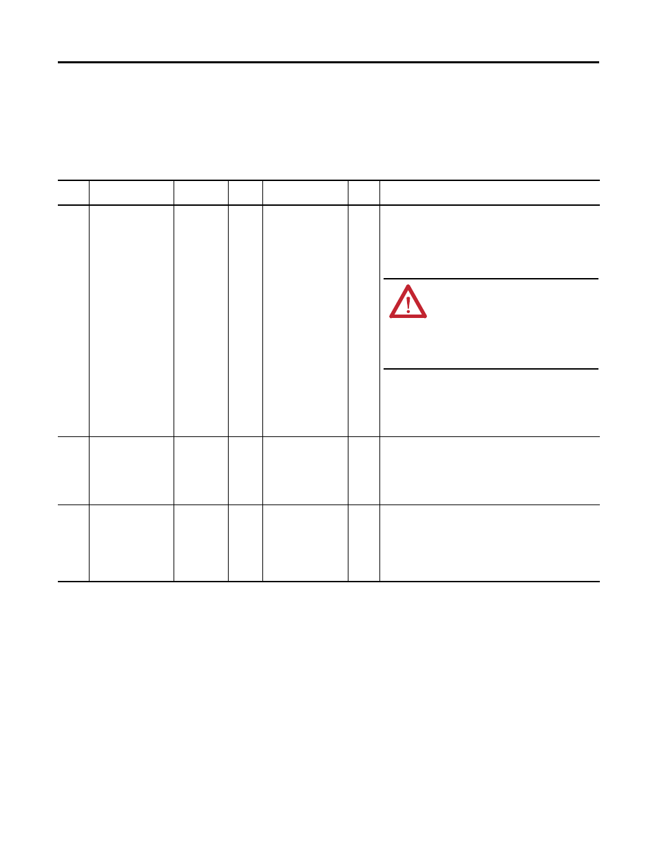
Table 12 - Inverter Fault and Alarm Types, Descriptions and Actions
Event
No.
Fault/Alarm Text
Type
Fault
Action
Configuration
Parameter
Auto
Reset
Description/Action(s)
10101
10201
10301
I1 Comm Loss
I2 Comm Loss
I3 Comm Loss
Non-Reset
Fault
Coast
Indicates that the communication connection from the fiber optic
interface board to the power layer interface board has been lost. Once
the root cause of the communication fault has been resolved, power
must be cycled or a drive reset must be initiated to clear this fault.
• Verify the status of the Fiber Loss pin segment of the power layer
interface board LED.
• Verify that the fiber optic cables are properly connected to the
transceivers.
• Verify that the transceivers are properly seated in the ports.
• Verify that the fiber optic cable is not cracked or broken.
• Verify that power is applied to the fiber optic interface board and
power layer interface board.
10102
10202
10302
I1 Thermal Const
I2 Thermal Const
I3 Thermal Const
Non-Reset
Fault
Coast
The thermal model data sent to the power layer interface board is
incorrect.
• Verify that the inverter is the correct rating for the drive.
• Compare the firmware versions of the power layer interface and
control board for compatibility.
• If necessary, re-flash the application firmware in control board.
10103
10203
10303
I1 HSFan Slow
I2 HSFan Slow
I3 HSFan Slow
Alarm 1
The inverter heatsink fan is running below normal operating speed.
• Verify the actual fan speed in [In HSFan Speed] (Port 10).
• Check for debris in the fan. If necessary, clean the fan and housing.
• Check for noise at the fan, indicating motor bearing failure.
• Verify that the fan power and feedback connections are not loose or
disconnected.
• Replace the fan, if necessary.
ATTENTION: Hazard of permanent eye damage
exists when using optical transmission
equipment. This product emits intense light and
invisible radiation. Do not look into fiber-optic
ports or fiber-optic cable connectors. Remove
power from the drive before disconnecting fiber
optic cables.