Drive fault and alarm descriptions – Rockwell Automation 21G PowerFlex 750-Series AC Drives Programming Manual User Manual
Page 313
Rockwell Automation Publication 750-PM001J-EN-P - October 2014
313
Troubleshooting
Chapter 6
Drive Fault and Alarm
Descriptions
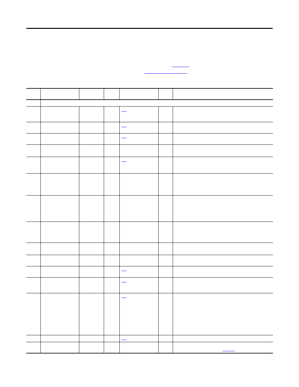
The table below contains a list of drive-specific faults and alarms, the type of fault
or alarm, the action taken when the drive faults, the parameter used to configure
the fault or alarm (if applicable), and a description and action (where applicable).
The faults and alarms listed in
Table 10
only apply to non Integrated Motion
applications. See
for a list of Integrated Motion faults.
Table 10 - Drive Fault and Alarm Types, Descriptions and Actions
Event
No.
Fault/Alarm Text
Type
Fault
Action
Configuration
Parameter
Auto
Reset
Description/Action(s)
0
No Entry
2
Auxiliary Input
Resettable
Fault
Coast
Y
An auxiliary input interlock is open. A condition within the application is
not allowing the drive to energize the motor and the digital input
assigned by P157 [DI Aux Fault] has forced this fault.
3
Power Loss
Configurable
[Power Loss Actn]
Y
The DC bus voltage remained below the [Pwr Loss n Level] of nominal
for longer than the time programmed in [Pwr Loss n Time].
4
UnderVoltage
Configurable
[UnderVltg Action]
Y
If the bus voltage, P11 [DC Bus Volts] falls below the value set in P461
[UnderVltg Level] an undervoltage condition exists.
5
OverVoltage
Resettable
Fault
Coast
Y
The DC bus voltage exceeded the maximum value.
See P11 [DC Bus Volts].
7
Motor Overload
Configurable
[Motor OL Actn]
Y
An internal electronic overload trip has occurred.
See P7 [Output Current], P26 [Motor NP Amps, P413 [Mtr OL Factor],
and/or P414 [Mtr OL Hertz].
8
Heatsink OvrTemp
Resettable
Fault
Coast
Y
The heatsink temperature has exceeded 100% of the drive temperature.
Heatsink over temperature occurs between 115…120 °C. The exact
value is stored in drive firmware.
See P943 [Drive Temp Pct] and/or P944 [Drive Temp C].
9
Trnsistr OvrTemp
Resettable
Fault
Coast
Y
The output transistors have exceeded the maximum operating
temperature.
See P941 [IGBT Temp Pct] and/or P942 [IGBT Temp C].
If using the drive on a chiller plate, P38 [PWM Frequency] must be set to
2 kHz.
10
DynBrake OvrTemp
Alarm 1
The dynamic brake resistor has exceeded its maximum operating
temperature.
Check settings of parameters P382 [DB Resistor Type] through P385 [DB
ExtPulseWatts].
12
HW OverCurrent
Resettable
Fault
Coast
Y
The drive output current has exceeded the hardware current limit.
Megger test wiring to motor.
13
Ground Fault
Resettable
Fault
Coast
Y
A current path to earth ground greater than 25% of drive rating has
occurred.
14
Ground Warning
Configurable
[Ground Warn Actn]
The ground current has exceeded the level set in P467 [Ground Warn
Lvl].
15
Load Loss
Configurable
The output torque current is below the value programmed in P442 [Load
Loss Level] for a time period greater than the time programmed in P443
[Load Loss Time].
17
Input Phase Loss
Configurable
The DC bus ripple has exceeded a preset level. Make these checks and
adjustments in this order.
• Check input impedance balance.
• Increase the setting of P463 [InPhase Loss Lvl] to make the drive less
sensitive.
• Tune the bus regulator or speed regulator to mitigate the affects of
dynamic cyclic loads on DC bus ripple.
• Disable the fault by setting P462 [InPhase LossActn] to 0 “Ignore”
and use an external phase loss detector such as a Bulletin 809S relay.
18
Motor PTC Trip
Configurable
[PTC Cfg]
Motor PTC (Positive Temperature Coefficient) over temperature.
19
Task Overrun
Alarm 1
System resource utilization is at or above 90% of capacity. Review the
system resource allocation table on
.