Rockwell Automation 21G PowerFlex 750-Series AC Drives Programming Manual User Manual
Page 100
100
Rockwell Automation Publication 750-PM001J-EN-P - October 2014
Chapter 3
Drive Port 0 Parameters
PR
O
TEC
TION
Load Limits
430
Current Limit Kp
Current Limit Proportional Gain
Proportional gain for the current limit function. This parameter is not functional when
any of the FV motor control modes are selected.
Units:
Default:
Min/Max:
Hz/A
290.0
0.0 / 1000000.0
RW Real
431
Id Lo FreqCur Kp
Id Low Frequency Current Kp
Current limit proportional gain active at very low operating frequencies. This parameter
is not functional when any of the FV motor control modes are selected.
Units:
Default:
Min/Max:
V/A
50.0
0.0 / 100000.0
RW Real
432
Iq Lo FreqCur Kp
Iq Low Frequency Current Kp
Current limit proportional gain active at very low operating frequencies. This parameter
is not functional when any of the FV motor control modes are selected.
Units:
Default:
Min/Max:
V/A
50.0
0.0 / 100000.0
RW Real
433
Jerk Gain
Jerk Gain
Allows you to adjust the amount of S Curve or “Jerk” applied to the Accel/Decel rate.
Default:
Min/Max:
5200.0
0.0 / 1000000000.0
RW Real
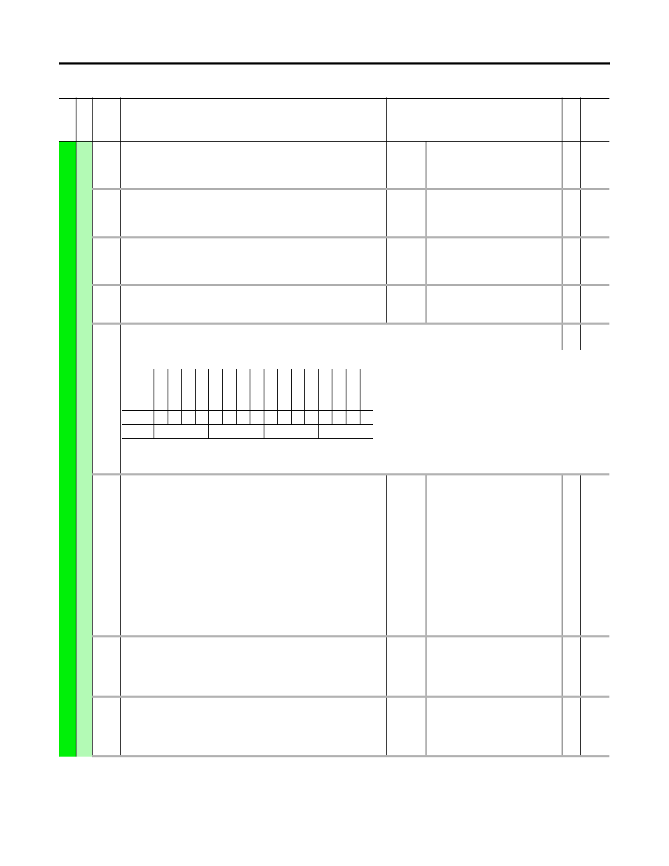
434
Shear Pin Cfg
Shear Pin Configure
RW 16-bit
Integer
Configures operation of the shear pin function.
Bit 0 “Shear1NoAcc” – 0 = Active during acceleration, 1 = Ignore during acceleration
Bit 1 “Shear2NoAcc” – 0 = Active during acceleration, 1 = Ignore during acceleration
435
438
Shear Pin 1 Actn
Shear Pin 2 Actn
Shear Pin n Action
Configures the action to take when the output current is greater than or equal to P436/
439 [Shear Pin n Level] for the amount of time set in P437/440 [Shear Pin n Time]. These
two independent shear pin functions can be set up to achieve the equivalent of external
overloads that have “stall” and “jam” indication.
“Ignore” (0) – No action is taken.
“Alarm” (1) – Type 1 alarm indicated.
“Flt Minor” (2) – Minor fault indicated. If running, drive continues to run.
Enable with P950 [Minor Flt Cfg]. If not enabled, acts like a major fault.
“FltCoastStop” (3) – Major fault indicated. Coast to Stop.
“Flt RampStop” (4) – Major fault indicated. Ramp to Stop.
“Flt CL Stop” (5) – Major fault indicated. Current Limit Stop.
Default:
Options:
0 = “Ignore”
0 = “Ignore”
1 = “Alarm”
2 = “Flt Minor”
3 = “FltCoastStop”
4 = “Flt RampStop”
5 = “Flt CL Stop”
RW 32-bit
Integer
436
439
Shear Pin1 Level
Shear Pin2 Level
Shear Pin n Level
Sets the value of current which will activate the shear pin function (see P435/438 [Shear
Pin n Actn]).
Units:
Default:
Min/Max:
Amps
P21 [Rated Amps]
0.0 / P21 [Rated Amps] x 1.5
RW Real
437
440
Shear Pin 1 Time
Shear Pin 2 Time
Shear Pin n Time
Sets the time associated with activation of the shear pin function (see P435/438 [Shear
Pin n Actn]).
Units:
Default:
Min/Max:
Secs
0.00
0.00 / 30.00
RW Real
Fi
le
Grou
p
No.
Display Name
Full Name
Description
Values
Re
ad
-W
ri
te
Da
ta
T
ype
Options
Re
ser
ve
d
Re
ser
ve
d
Re
ser
ve
d
Re
ser
ve
d
Re
ser
ve
d
Re
ser
ve
d
Re
ser
ve
d
Re
ser
ve
d
Re
ser
ve
d
Re
ser
ve
d
Re
ser
ve
d
Re
ser
ve
d
Re
ser
ve
d
Re
ser
ve
d
Sh
ea
r2No
Ac
c
Sh
ea
r1No
Ac
c
Default
0
0
0
0
0
0
0
0
0
0
0
0
0
0
0
0
Bit
15 14 13 12 11 10 9
8
7
6
5
4
3
2
1
0