Torque control – c urrent, Figure 58 - torque control - current (im & spm) – Rockwell Automation 21G PowerFlex 750-Series AC Drives Programming Manual User Manual
Page 424
424
Rockwell Automation Publication 750-PM001J-EN-P - October 2014
Appendix A
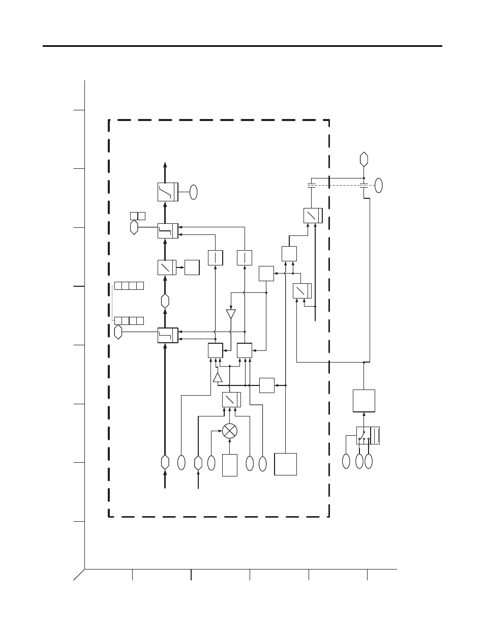
PowerFlex 755 Control Block Diagrams
Figure 58 - Torque Control - Current (IM & SPM)
1
2
3
4
5
6
B
A
D
C
F
E
H
G
I
Torque Control –
C
urrent
Induction Motor (IM) & Surface
Permanent Magnet Motor (SPM)
PF
755 Rev
_10.a
Page
24a
Power
Unit
Thermal
Protection
Calc
Is,Id
Iq
Pos Torque
Limi
t
{Trq
Neg Lm
t}
Neg Torque Limit
{Trq
Pos Lm
t}
R
ege
n Po
we
r
Lm
t
{Re
gen Pwr
Lmt}
Bu
s
Regulator
Ca
lc
Pw
r
Te
Active Vel
Fdbk
Activ
e Pos
Torqu
e Limit
Active
Neg
T
orque L
imit
Lim
it
Ma
x
Min
Filtered Trq
Re
f
Limited Trq
Ref
Motor Ctrl Mode
Flux Current
Fdbk
Ca
lc
Iq,Id
Is
Active Cur Lm
t
Li
mit
Calc
Te
Iq
Rate
Lim
Mot
or Power Lm
t
{Mtrng
PwrLm
t}
To
rque Current Re
f
Current Rate Lmt
Min
Pk To
rque Iq
Curren
t Limit
Voltag
e Ref/
Limit
Gene
ration
Current Lmt 1
Current Lmt Sel
Curr
ent Lmt 2
Ac
tive Iq
Current
Limit
T
herma
l Mgr C
urrent
Limit
424
42
1
42
2
42
3
425
690
689
+
+
35
13
1
42
6
427
671
670
Neg
Li
mit
Pos
Limit
V
F
or SV
(0-2,4,
5,7,8)
Flux V
ector
(3,6
)
945
21
At Limit Status
22
Trq
Pos Lm
t
T
rq Neg
Lmt
945
17
At
Limit
Status
18
TrqC
urPosLm
t
TrqCu
rNegLm
t
Flux Vector
Par
ameter
Se
lection
From Fdbk
[3
F2
]
[3
6D
2]
From Torq
Ctrl
[23H2]
[3C6
], [2
5E2],
[26E2]
1
Fl
ux
1
Fl
ux
-1
Flux
-1
Flux
23
24
Mtrng P
wrLm
t
R
egen Pw
rLmt
25
26
Cur Lmt
FV
Therm
RegL
m
t
27
28
Bus
VltgFVL
mt
Mtr
Vltg Lk
g
Flu
x
{B
usVltg
FVLmt
}
{Mt
r Vltg L
kg}
{Cur
Lmt F
V
}
{T
herm R
egLmt
}