Diagnostic tools, Figure 74 - diagnostic tools, Peak detect – Rockwell Automation 21G PowerFlex 750-Series AC Drives Programming Manual User Manual
Page 440: Digital switches
440
Rockwell Automation Publication 750-PM001J-EN-P - October 2014
Appendix A
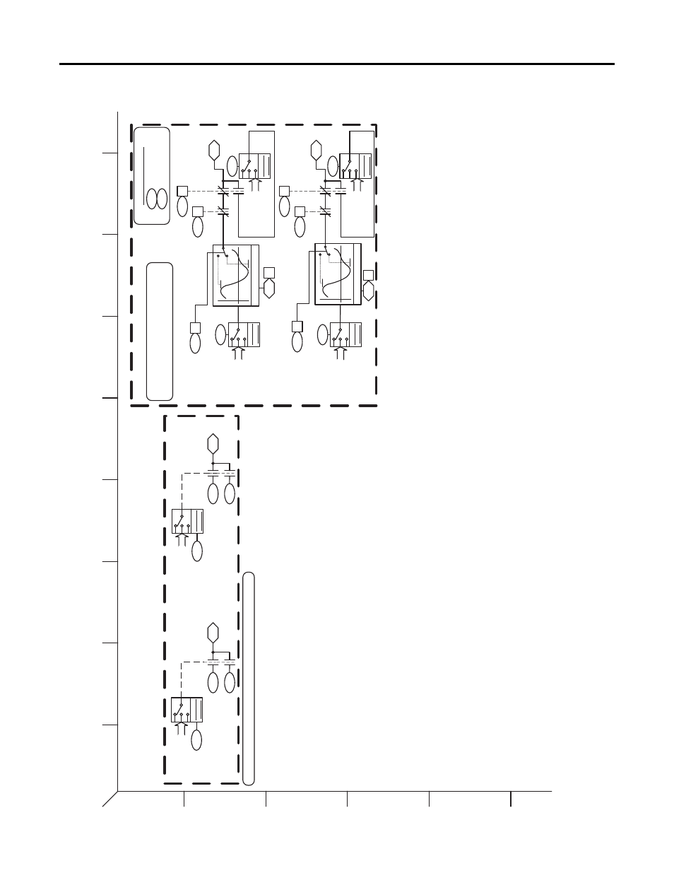
PowerFlex 755 Control Block Diagrams
Figure 74 - Diagnostic Tools
1
2
3
4
5
6
B
A
D
C
F
E
H
G
I
10
39
0
Pea
k 1 Cha
nge
(Pea
k1
C
hange)
Peak1 Cfg
(Pea
k1
Peak)
PeakDe
tect1 Out
Pe
ak1 Cfg
(P
eak1 Hold)
Peak1 Cfg
(Peak1 Set)
NOTE:
T
he chan
ge bit, P
eak x C
hng (w
here x = 1 or
2), is
set TR
UE if t
he
pe
ak detec
t value
changes
, else th
e change
bit is s
et FAL
SE.
C
hange is
also se
t to FA
LSE if t
he detec
tor is i
n HOLD
or SE
T.
1040
0
10
39
1
10
39
2
10
41
Peak Dete
ct
Peak 2 Change (Peak2Change)
PeakDe
tect2 Out
Pe
ak2 Cfg
(Peak2 Hold)
Peak2 Cfg
(Peak2 Set)
10
45
0
10
44
1
10
44
2
10
46
Peak Detect
Numeric Constants
PkDtct Stpt Real
1
035
PkDtct Stpt Dint
103
6
d57
Dig Sw
Rea
l Sel
d60
Dig
Sw Re
al
Ou
t
0
1
d58
Sw
O
ff Stpt
R
ea
l
d59
Sw On Stpt Real
Bit
Source
d6
1
Dig S
w
Dint Sel
d64
Dig Sw Dint Out
0
1
d6
2
Sw Off Stpt Dint
d6
3
Sw On Stpt Dint
Bit
Source
Digital Switches
Bit To Numeri
c Conversion
10
38
PkDtct1
PresetSe
l
Pe
ak
1
Pres
et
D
a
ta
Source
(numeric)
PkDtct1 In Sel
Pe
ak
1
Inpu
t Da
ta
Sour
ce
(n
umeric)
PkDtct2
PresetSel
Peak 2
Pr
ese
t Da
ta
Source
(num
eric
)
Real
Real
on
off
1044
0
Peak2 Cfg
(P
eak2
P
e
ak
)
Peak Detect
1042
P
kDtct2 In Sel
Peak 2
Input Data
Source
(numeric)
Real
on
off
Diagnostic Tools
Pa
ramete
r
S
election
Param
eter
Select
ion
Param
eter
Selec
tion
1037
Pa
ramete
r
S
election
Param
eter
Sele
ction
10
43
Real
Param
eter
Sele
ction
‘d’ Prefix Refers to
Di
agnostic Item Number (ex. d33
) –
R
eference Symbol Legend
PF
755 Rev
_10.a
Pag
e 39