Rockwell Automation 21G PowerFlex 750-Series AC Drives Programming Manual User Manual
Page 331
Rockwell Automation Publication 750-PM001J-EN-P - October 2014
331
Troubleshooting
Chapter 6
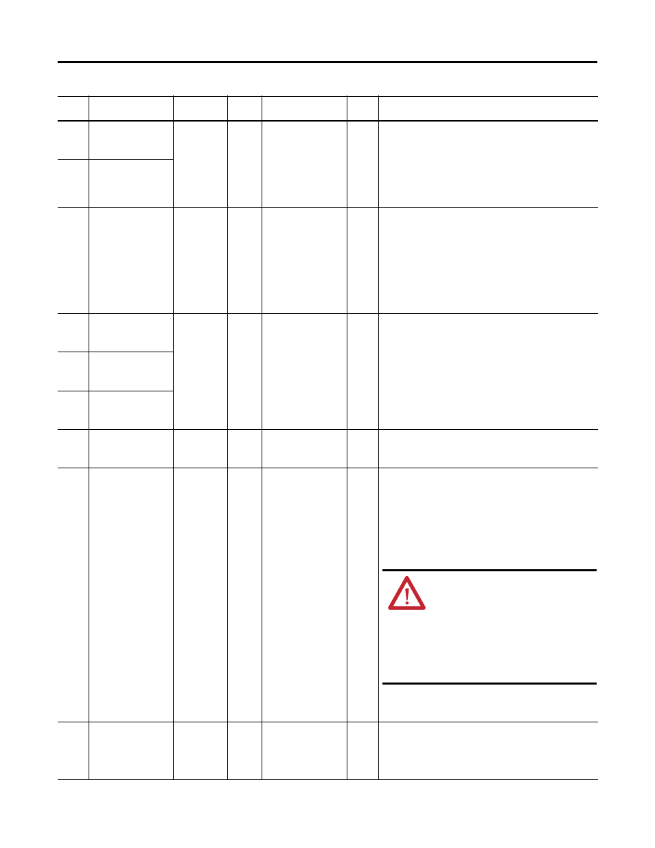
10122
10222
10322
I1 InFan1 Slow
I2 InFan1 Slow
I3 InFan1 Slow
Alarm 1
Stirring fan 1 is under speed.
• Visually verify that fan 1 is turning.
• Check the measured fan speed in [In InFan n Speed] (port 10).
• Check the wiring harness to the stirring fans to verify that the power
and tachometer signals are connected.
• If necessary, replace both stirring fans. When the fans are replaced,
the elapsed hours, displayed in [In PredMainReset] (port 10) must be
reset.
10123
10223
10323
I1 InFan2 Slow
I2 InFan2 Slow
I3 InFan2 Slow
10124
10224
10324
I1 NTC Open
I2 NTC Open
I3 NTC Open
Non-Reset
Fault
Coast
An NTC open condition has occurred.
• Check the ribbon cable that runs between the backplane board and
gate driver board for loose connections or damage. The capacitor
bank must be removed in order to check this cable.
• If the drive is located in extremely cold conditions, raise the ambient
temperature.
• Check the power layer interface board testpoints for the individual
phase NTC temperatures to determine which is open.
• Re-seat the power layer interface board. If this problem persists,
replace the power layer interface board.
10125
10225
10325
I1 Incompat UBrd
I2 Incompat UBrd
I3 Incompat UBrd
Non-Reset
Fault
Coast
The power layer interface and power control board do not detect the
correct gate driver board on the U, V, or W phase. This fault may occur
during a normal power down sequence.
• Check the ribbon cable that runs between the backplane board and
gate driver board for loose connections or damage and verify that the
correct gate driver board is installed. The capacitor bank must be
removed in order to check this cable and the board.
• Re-flash the control board.
• Check the rating plug.
10126
10226
10326
I1 Incompat VBrd
I2 Incompat VBrd
I3 Incompat VBrd
10127
10227
10327
I1 Incompat WBrd
I2 Incompat WBrd
I3 Incompat WBrd
10128
10228
10328
I1 Incompat Brdn
I2 Incompat Brdn
I3 Incompat Brdn
Non-Reset
Fault
Coast
The drive detected an incompatible burden resistor.
• Verify that the correct rating plug in installed. Re-seat the rating
plug.
10129
10229
10329
I1 DC Bus Imbal
I2 DC Bus Imbal
I3 DC Bus Imbal
Resettable
Fault
Coast
Either the lower or upper leg of the capacitor bank is getting too much
voltage (based on the bus voltage, measured voltage across the lower
leg, and a calculation to find the voltage across the upper leg) or the
voltage sensing components are damaged.
• Check the value of the bus bleeder resistor and bus balancing resistor
and replace as necessary.
• Inspect the capacitor bank for leakage or damage and replace as
necessary. Replacing the capacitor bank assembly will also replace
the bus balancing resistor.
• Measure the voltage on each half of the bus to confirm the
calculations. If the bus measurements aren’t correct, replace the
power interface board and/or inverter power supply board.
10130
10230
10330
I1 Curr Offset
I2 Curr Offset
I3 Curr Offset
Alarm 1
The calculated current offset for any phase is larger than expected.
• Check the current sensor’s offset reading inverter testpoint and
power supply. If necessary, replace the current sensor.
• If this problem persists, replace the inverter power supply board and/
or the power layer interface board.
Event
No.
Fault/Alarm Text
Type
Fault
Action
Configuration
Parameter
Auto
Reset
Description/Action(s)
ATTENTION: The DC bus voltage can only be
measured when the drive is energized. Servicing
energized equipment can be hazardous. Severe
injury or death can result from electrical shock,
burn or unintended actuation of controlled
equipment. Follow Safety related practices of
NFPA 70E, ELECTRICAL SAFETY FOR EMPLOYEE
WORKPLACES. DO NOT work alone on energized
equipment!