Embedded devicelogix (port 14) parameters – Rockwell Automation 21G PowerFlex 750-Series AC Drives Programming Manual User Manual
Page 243
Rockwell Automation Publication 750-PM001J-EN-P - October 2014
243
Embedded Feature and Option Module Parameters
Chapter 5
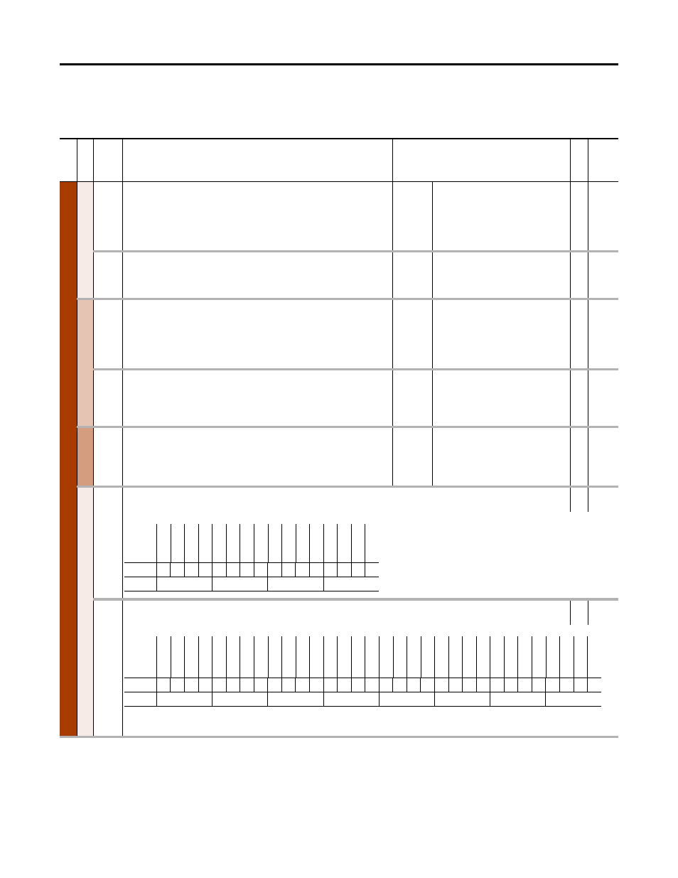
Embedded DeviceLogix (Port
14) Parameters
Fil
e
Gr
oup
No.
Display Name
Full Name
Description
Values
Re
ad
-Write
Da
ta
T
yp
e
Embe
dded De
viceL
og
ix
A
n
alog
O
u
tpu
ts
1
Thru
14
DLX Out 01
DLX Out 14
Fourteen floating point outputs that can be controlled by the DeviceLogix program.
These are typically mapped to a parameter to write its value. It can also be mapped to
the Reference Command.
Default:
Min/Max:
0
0 / 159999
RW 32-bit
Real
15
16
DLX Out 15
DLX Out 16
Two unsigned 32-bit integer outputs that can be controlled by the DeviceLogix program.
These are typically mapped to a parameter to write its value.
Default:
Min/Max:
0
0 / 159999
RW 32-bit
Integer
Analog Inputs
17
Thru
30
DLX In 01
DLX In 14
Fourteen floating point inputs that can be read by the DeviceLogix program. These are
typically mapped to a parameter to read its value. It can also be mapped to Common
Feedback.
Default:
Min/Max:
0
0 / 159999
RW 32-bit
Real
31
32
DLX In 15
DLX In 16
Two unsigned 32-bit integer inputs that can be read by the DeviceLogix program. These
are typically mapped to a parameter to read its value. It can also be mapped to Real
Time Clock values.
Default:
Min/Max:
0
0 / 159999
RW 32-bit
Integer
Digi
tal In
puts
33
Thru
48
DLX DIP 01
DLX DIP 16
Sixteen digital inputs that can be read by the DeviceLogix program. These are typically
mapped to an input point in an I/O option module or to Logic Status bits.
Default:
Min/Max:
0.00
0 / 159999.15
RW 32-bit
Integer
Sta
tus
&
Cntl
49
DLX DigIn Sts
Provides the individual on/off status of the 16 DLX DIP's.
RO
16-bit
Integer
50
DLX DigOut Sts
Provides the individual on/off status of the DLX Logic Command word bits.
RO
32-bit
Integer
Options
DL
X D
IPV
al
16
DL
X D
IPV
al
15
DL
X D
IPV
al
14
DL
X D
IPV
al
13
DL
X D
IPV
al
12
DL
X D
IPV
al
11
DL
X D
IPV
al
10
DL
X D
IPV
al
9
DL
X D
IPV
al
8
DL
X D
IPV
al
7
DL
X D
IPV
al
6
DL
X D
IPV
al
5
DL
X D
IPV
al
4
DL
X D
IPV
al
3
DL
X D
IPV
al
2
DL
X D
IPV
al
1
Default
0
0
0
0
0
0
0
0
0
0
0
0
0
0
0
0
Bit
15 14 13 12 11 10 9
8
7
6
5
4
3
2
1
0
0 = Condition Off
1 = Condition On
Options
Re
se
rv
ed
Re
se
rv
ed
Re
se
rv
ed
Re
se
rv
ed
Re
se
rv
ed
Re
se
rv
ed
Re
se
rv
ed
Re
se
rv
ed
Re
se
rv
ed
Re
se
rv
ed
Re
se
rv
ed
Re
se
rv
ed
Re
se
rv
ed
Re
se
rv
ed
Re
se
rv
ed
Re
se
rv
ed
DLX
CmdSts
16
DLX
CmdSts
15
DLX
CmdSts
14
DLX
CmdSts
13
DLX
CmdSts
12
DLX
CmdSts
11
DLX
CmdSts
10
DLX
CmdSts
9
DLX
CmdSts
8
DLX
CmdSts
7
DLX
CmdSts
6
DLX
CmdSts
5
DLX
CmdSts
4
DLX
CmdSts
3
DLX
CmdSts
2
DLX
CmdSts
1
Default
0
0
0
0
0
0
0
0
0
0
0
0
0
0
0
0
0
0
0
0
0
0
0
0
0
0
0
0
0
0
0
0
Bit
31 30 29 28 27 26 25 24 23 22 21 20 19 18 17 16 15 14 13 12 11 10 9
8
7
6
5
4
3
2
1
0
0 = Condition Off
1 = Condition On