Rockwell Automation 21G PowerFlex 750-Series AC Drives Programming Manual User Manual
Page 283
Rockwell Automation Publication 750-PM001J-EN-P - October 2014
283
Embedded Feature and Option Module Parameters
Chapter 5
Un
iv
ersal F
eedback
Feedback 1
38
FB1 Cfg
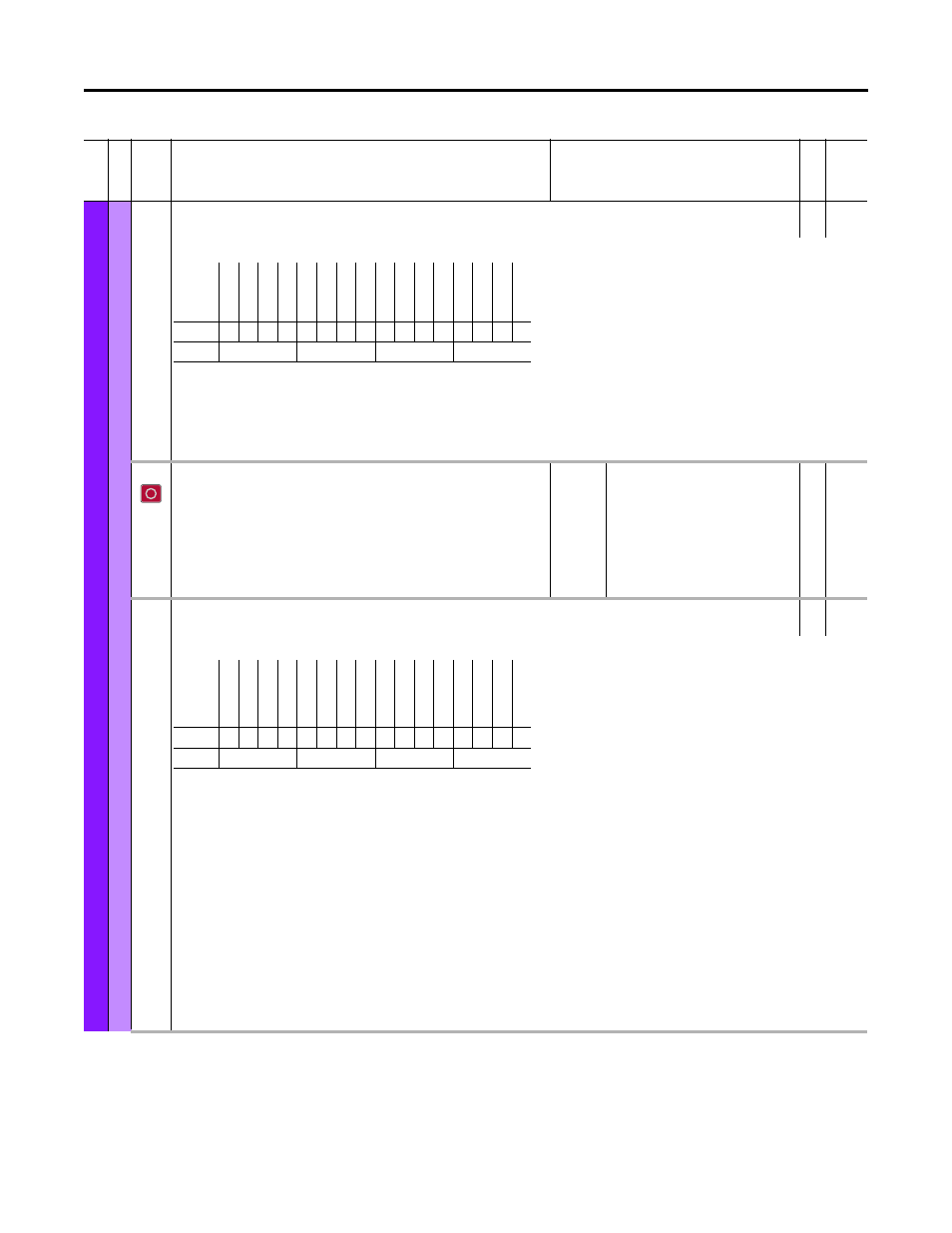
Feedback 1 Configuration
RW 16-bit
Integer
Configure the direction, position data format, as well as the baud rate for the serial communication interface for the feedback 1 device.
Bit 0 “Direction” – Inverts the direction internally.
Bit 1 “24-bit Resol” – If set, the data format of the parameter [FB1 Position] is set to 8/24 (8 bit resolution, 24 bits position within one revolution). Otherwise, the
data format is set to 12/20. It only makes sense to set this bit if the bit “Enh Resol” in parameter [FB1 Identify] is set.
Bit 2 “FD Low Baud” – Reduces the communication baud rate from the default setting for the connected encoder with a serial communication channel.
Bit 3 “SC Quadrant” – Reserved for future use.
39
FB1 Loss Cfg
Feedback 1 Loss Configuration
Configures how the drive reacts to an error status condition on the feedback 1 device.
“Ignore” (0) – No action is taken.
“Alarm” (1) – Type 1 alarm indicated.
“Flt Minor” (2) – Minor fault indicated. If running, drive continues to run.
Enable with P950 [Minor Flt Cfg]. If not enabled, acts like a major fault.
“FltCoastStop” (3) – Major fault indicated. Coast to Stop.
Default:
Options:
3 = “FltCoastStop”
0 = “Ignore”
1 = “Alarm”
2 = “Flt Minor”
3 = “FltCoastStop”
RW 32-bit
Integer
40
FB1 Sts
Feedback 1 Status
RO
16-bit
Integer
Shows feedback specific errors and alarms for the feedback 1 device.
Bit 0 “Encoder Err” – When asserted, there is an Encoder Error.
Bit 1 “Msg Checksum” – When asserted, the module has experienced a checksum error while attempting to communicate to an encoder via the serial
communication channel.
Bit 2 “Timeout” – When asserted, the module has experienced a time out condition while attempting to communicate to the encoder via the serial communication
channel.
Bit 3 “Comm” – When asserted, there was an error (except Checksum and Time Out) while attempting to communicate to an encoder via the serial communication
channel.
Bit 4 “Diagnostic” – When asserted, the module has experienced a diagnostic test failure on power up.
Bit 5 “SpplyVltRng” – When asserted, the voltage source to the encoder is out of range.
Bit 6 “SC Amplitude” – When asserted, the module detected that the encoder signal amplitude is out of tolerance.
Bit 7 “Open Wire” – When asserted, the module has detected an open wire.
Bit 8 “Quad Loss” – Indicates that there is a signal quadrature error.
Bit 9 “Phase Loss” – Indicates that an A or B signal of an A Quad B Incremental encoder is disconnected.
Bit 10 “Unsupp Enc” – Indicates that the connected encoder is not supported.
Bit 12 “Encoder Alm” – When asserted, there is an Encoder Alarm.
Fi
le
Grou
p
No.
Display Name
Full Name
Description
Values
Re
ad
-W
ri
te
Da
ta
T
ype
Options
Re
ser
ve
d
Re
ser
ve
d
Re
ser
ve
d
Re
ser
ve
d
Re
ser
ve
d
Re
ser
ve
d
Re
ser
ve
d
Re
ser
ve
d
Re
ser
ve
d
Re
ser
ve
d
Re
ser
ve
d
Re
ser
ve
d
SC Q
uadr
ant
FD
L
ow Ba
ud
24
-bit Resol
Di
re
ct
io
n
Default
0
0
0
0
0
0
0
0
0
0
0
0
0
0
0
0
Bit
15 14 13 12 11 10 9
8
7
6
5
4
3
2
1
0
0 = Condition False
1 = Condition True
Options
Res
er
ved
Res
er
ved
Res
er
ved
En
co
de
r A
lm
Res
er
ved
Un
su
pp
En
c
Ph
as
e L
os
s
Qu
ad
L
os
s
Open
W
ire
SC Amplitude
Sp
plyV
ltR
ng
Dia
gnosti
c
Co
m
m
Ti
meout
Ms
g Ch
ec
ksu
m
En
co
de
r E
rr
Default
0
0
0
0
0
0
0
0
0
0
0
0
0
0
0
0
Bit
15 14 13 12 11 10 9
8
7
6
5
4
3
2
1
0
0 = Condition False
1 = Condition True