Control logic, Figure 70 - control logic – Rockwell Automation 21G PowerFlex 750-Series AC Drives Programming Manual User Manual
Page 436
436
Rockwell Automation Publication 750-PM001J-EN-P - October 2014
Appendix A
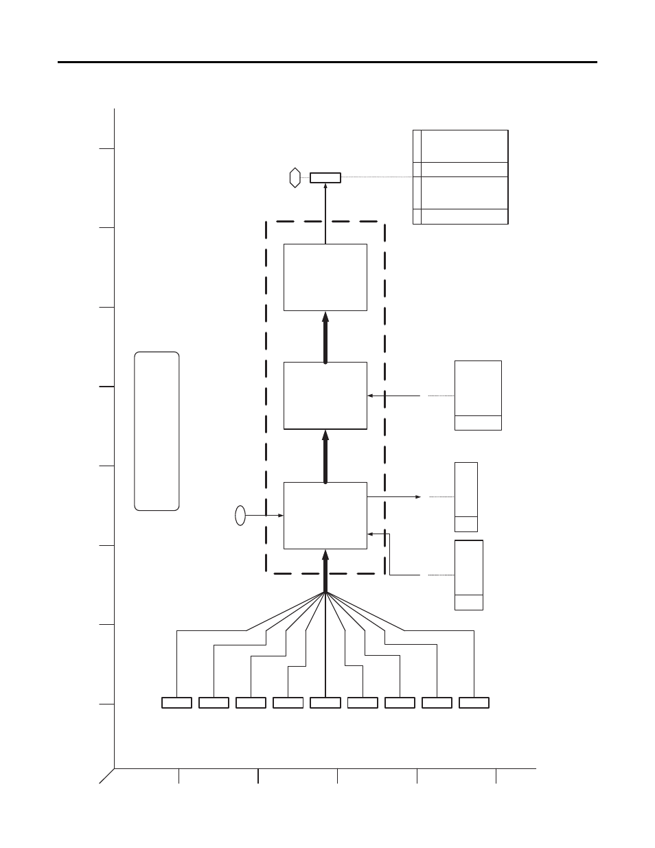
PowerFlex 755 Control Block Diagrams
Figure 70 - Control Logic
1
2
3
4
5
6
B
A
D
C
F
E
H
G
I
Control Logic
DPI Port 2
0
15
DPI Port 4
0
15
DPI Port 3
0
15
DPI Port 1
(Drv Mounted HIM)
0
15
Di
git
a
l Inp
u
ts
0
15
DPI Port 6
0
15
Dev
ice
Log
ix
Po
rt
1
4
0
15
Embedded
Ethernet
Po
rt
1
3
0
15
DPI Port 5
0
15
Mask Eval
uation
Logic
Ma
sk
s
Logic Mask
Auto Mask
Manual Cmd Mask
Manual Ref Mask
32
4
325
32
6
32
7
Owner Lo
gic
Logic Evaluation
879
Drive Logic Rslt
Owners
Stop Owner
Start Owner
Jo
g Own
er
Dir Owner
Clear Flt Own
er
Manual Owner
Ref Select Owner
919
920
921
92
2
923
924
925
Logic Parser
0
31
Stop
Start
Jog1
Clear F
aults
Forwa
rd
Revers
e
Manual
Reserv
ed
Accel T
ime 1
Accel T
ime 2
Decel Time
1
Decel Time
2
SpdRef
Sel 0
SpdRef
Sel 1
SpdRef
Sel 2
Reserv
ed
00
01
02
03
04
05
06
07
08
09
10
11
12
13
14
15
Bit
Coas
t Stop
Curr
Lim St
op
Run
Jog 2
Rese
rved
Rese
rved
Rese
rved
Rese
rved
Rese
rved
Rese
rved
Rese
rved
Rese
rved
Rese
rved
Rese
rved
Rese
rved
Rese
rved
16
17
18
19
20
21
22
23
24
25
26
27
28
29
30
31
Bit
Masks Act St
at
us
Port Mask Act
Logic Mask Act
Write Mask Act
885
886
887
Write Mask Cfg
Note:
The following parameters are typically referenced
when configuring or moni
toring Control Logic;
P933 [Start Inhibits]
To Spd Ref
[5G2], [6E3], [7F2],
[7F3], [8F2], [8F3]
888
PF
755 Rev
_10.a
Pag
e 35