Rockwell Automation 21G PowerFlex 750-Series AC Drives Programming Manual User Manual
Page 265
Rockwell Automation Publication 750-PM001J-EN-P - October 2014
265
Embedded Feature and Option Module Parameters
Chapter 5
Fil
e
Gr
ou
p
No.
Display Name
Full Name
Description
Values
Re
ad
-Write
Da
ta T
ype
22
-Serie
s I/O
Predi
ct
iv
e M
ain
99
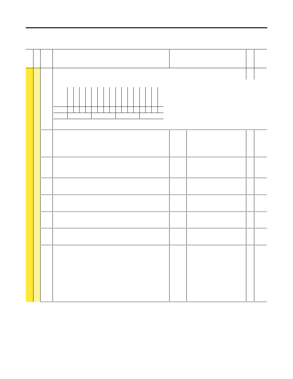
PredMaint Sts
Predictive Maintenance Status
RO
16-bit
Integer
Status of relay's predictive maintenance.
(1) Bit 1= “Relay Out 0” for 22-Series I/O Module models 20-750-2262C-2R and 20-750-2262D-2R
100
RO0 Load Type
Relay Output 0 Load Type
Sets the type of load that will be applied to the relay. Must be properly set for the
Predictive Maintenance function to predict the relay life.
Default:
Options:
1 = “DC Inductive”
0 = “DC Resistive”
1 = “DC Inductive”
2 = “AC Resistive”
3 = “AC Inductive”
RW 32-bit
Integer
101
RO0 Load Amps
Relay Output 0 Load Amps
Load current that will be applied to the relay contacts. Must be properly set for the
Predictive Maintenance function to approximate the relay life.
Units:
Default:
Min/Max:
Amps
2.000
0.000 / 2.000
RW Real
102
RO0 TotalLife
Relay Output 0 Total Life
Total life cycles of the relay based on programmed load type and amps.
Units:
Default:
Min/Max:
Cycl
0
0 / 2147483647
RO
32-bit
Integer
103
RO0 ElapsedLife
Relay Output 0 Elapsed Life
Non-resettable, total accumulated cycles of the relay.
Units:
Default:
Min/Max:
Cycl
0
0 / 2147483647
RO
32-bit
Integer
104
RO0 RemainLife
Relay Output 0 Remaining Life
The difference between the Total Life and the Elapsed Life.
Units:
Default:
Min/Max:
Cycl
0
–/+2147483647
RO
32-bit
Integer
105
RO0 LifeEvntLvl
Relay Output 0 Life Event Level
Sets the percentage of relay life cycles before action is taken.
Units:
Default:
Min/Max:
%
80.000
0.000 / 100.000
RW Real
106
RO0 LifeEvntActn
Relay Output 0 Life Event Action
Sets the action that will be taken when the percentage of relay life cycles has been
reached.
“Ignore” (0) – No action is taken.
“Alarm” (1) – Type 1 alarm indicated.
“Flt Minor” (2) – Minor fault indicated. If running, drive continues to run.
Enable with P950 [Minor Flt Cfg]. If not enabled, acts like a major fault.
“FltCoastStop” (3) – Major fault indicated. Coast to Stop.
“Flt RampStop” (4) – Major fault indicated. Ramp to Stop.
“Flt CL Stop” (5) – Major fault indicated. Current Limit Stop.
Default:
Options:
1 = “Alarm”
0 = “Ignore”
1 = “Alarm”
2 = “Flt Minor”
3 = “FltCoastStop”
4 = “Flt RampStop”
5 = “Flt CL Stop”
RW 32-bit
Integer
Options
Mast
er
Re
se
rv
ed
Re
se
rv
ed
Re
se
rv
ed
Re
se
rv
ed
Re
se
rv
ed
Re
se
rv
ed
Re
se
rv
ed
Re
se
rv
ed
Re
se
rv
ed
Re
se
rv
ed
Re
se
rv
ed
Re
se
rv
ed
Re
se
rv
ed
Re
la
y Out
0
(1
)
Re
la
y Out
0
Default
0
0
0
0
0
0
0
0
0
0
0
0
0
0
0
0
Bit
15 14 13 12 11 10 9
8
7
6
5
4
3
2
1
0
0 = Condition False
1 = Condition True