Rockwell Automation 21G PowerFlex 750-Series AC Drives Programming Manual User Manual
Page 245
Rockwell Automation Publication 750-PM001J-EN-P - October 2014
245
Embedded Feature and Option Module Parameters
Chapter 5
Embedde
d De
viceL
ogix
Int
ernal Regs
54
Thru
69
DLX Real SP1
DLX Real SP16
Sixteen 32-bit Real scratchpad registers for DLX program use.
Default:
Min/Max:
0
–/+220000000
RW Real
70
Thru
77
DLX DINT SP1
DLX DINT SP8
Eight 32-bit Integer scratchpad registers for DLX program use.
Default:
Min/Max:
0
–2147483648 / 2147483647
RW 32-bit
Integer
78
Thru
81
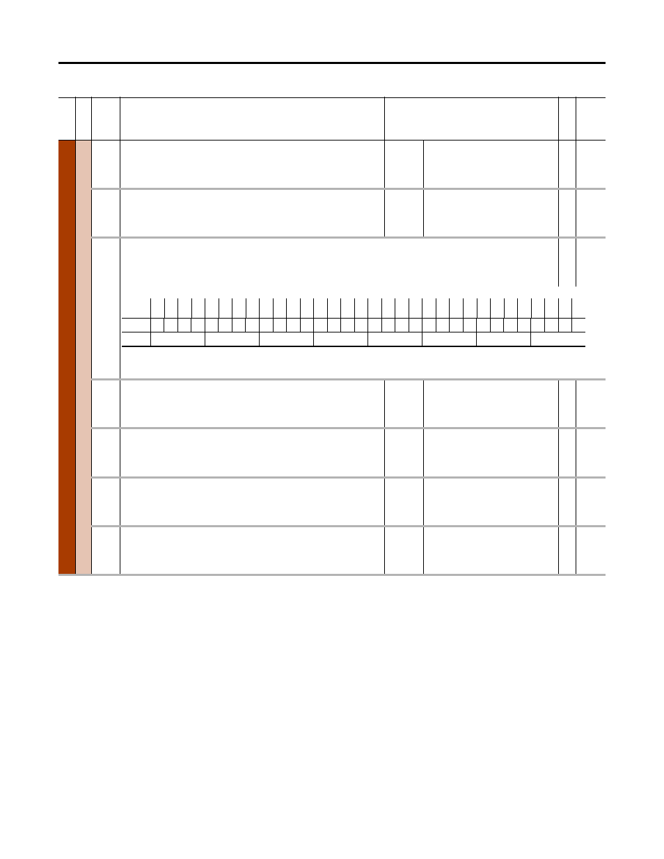
DLX Bool SP1
DLX Bool SP4
Four 32-bit Boolean scratchpad registers (128 bits total) for DLX program use.
RW 32-bit
Integer
82
Thru
89
DLX Real In SP1
DLX Real In SP8
Eight 32-bit Real scratchpad registers for DLX program input use.
Default:
Min/Max:
0
–/+220000000
RW Real
90
Thru
97
DLX Real OutSP1
DLX Real OutSP8
Eight 32-bit Real scratchpad registers for DLX program output use.
Default:
Min/Max:
0
–/+220000000
RW Real
98
Thru
101
DLX DINT InSP1
DLX DINT InSP4
Four 32-bit Integer scratchpad registers for DLX program input use.
Default:
Min/Max:
0
–2147483648 / 2147483647
RW 32-bit
Integer
102
Thru
105
DLX DINT OutSP1
DLX DINT OutSP4
Four 32-bit Integer scratchpad registers for DLX program output use.
Default:
Min/Max:
0
–2147483648 / 2147483647
RW 32-bit
Integer
Fi
le
Grou
p
No.
Display Name
Full Name
Description
Values
Re
ad
-W
ri
te
Da
ta
T
ype
Options
Bit
31
Bit
30
Bit
29
Bit
28
Bit
27
Bit
26
Bit
25
Bit
24
Bit
23
Bit
22
Bit
21
Bit
20
Bit
19
Bit
18
Bit
17
Bit
16
Bit
15
Bit
14
Bit
13
Bit
12
Bit
11
Bit
10
Bit
9
Bit
8
Bit
7
Bit
6
Bit
5
Bit
4
Bit
3
Bit
2
Bit
1
Bit
0
Default 0
0
0
0
0
0
0
0
0
0
0
0
0
0
0
0
0
0
0
0
0
0
0
0
0
0
0
0
0
0
0
0
Bit
31 30 29 28 27 26 25 24 23 22 21 20 19 18 17 16 15 14 13 12 11 10 9
8
7
6
5
4
3
2
1
0
0 = Condition Off
1 = Condition On