Rockwell Automation 21G PowerFlex 750-Series AC Drives Programming Manual User Manual
Page 175
Rockwell Automation Publication 750-PM001J-EN-P - October 2014
175
Drive Port 0 Parameters
Chapter 3
Fil
e
Gr
ou
p
No.
Display Name
Full Name
Description
Values
Re
ad
-Write
Da
ta T
ype
APPLIC
AT
IONS
To
rq
ue
P
ro
ve
1100
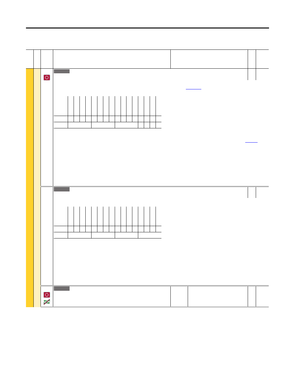
Trq Prove Cfg
Torque Prove Configure
RW 16-bit
Integer
Enables/disables torque/brake proving function. When “Enabled,” brake control comes from a digital output relay that is set to select Port 0, P1103 [Trq Prove
Status] Bit 4 “Brake Set.” Refer to the PowerFlex 750-Series AC Drives Reference Manual, publication
, for examples on how to use Torque Prove with
PowerFlex 755 drives.
Bit 0 “TP Enable” – Enables TorqProve functions.
Bit 1 “Encoderless” – Enables encoderless operation – Bit 0 must also be enabled. Read the Attention statement under Lifting/Torque Proving on
Bit 2 “Micro Psn” – Enables the Micro Position digital input to change the speed command by the value set in P1112 [MicroPsnScalePct] while the drive is running.
Bit 3 “Preload” – “0” uses the last torque for preload. “1” uses “TorqRef A” if commanded direction is forward and “TorqRef B” for reverse.
Bit 4 “FW LoadLimit” – Enables drive to perform load calculation at base speed. Drive will then limit operation above base speed depending on load.
Bit 5 “BrkSlipEncls” – A “1” Disables the partial Brake Slip routine from the drive when encoderless is selected.
Bit 6 “BrkSlipStart” – Starts drive if Brake slippage is detected.
Bit 7 “Test Brake” – Tests the brake at Start. Torque is applied against the brake while movement is monitored.
Bit 8 “Fast Stop Bk” – Brake is set immediately upon receiving a Fast Stop input vs. setting the brake after the ramp.
Bit 9 “BkSlp SpdLmt” – When a brake slip condition is detected, the load is lowered at a fixed speed (Preset Speed 1).
1101
Trq Prove Setup
Torque Prove Setup
RW 16-bit
Integer
Allows control of specific torque proving functions through a communication device.
Bit 0 “Fast Stop” – Forces a current limit stop.
Bit 1 “Float Micro” – Activates the micro position function when selected and running. Activates float when stopping.
Bit 2 “Decel Fwd” – Forces decel forward travel limit.
Bit 3 “End Stop Fwd” – Forces end forward travel limit.
Bit 4 “Decel Rev” – Forces decel reverse travel limit.
Bit 5 “End Stop Rev” – Forces end reverse travel limit.
Bit 6 “PHdwrOvrTrvl” – Positive Hardware Over Travel limit: Setting this bit creates a Coast to Stop fault.
Bit 7 “NHdwrOvrTrvl” – Negative Hardware Over Travel limit: Setting this bit creates a Coast to Stop fault.
1102
DI FloatMicroPsn
Digital Input Float Micro Position
Selects the digital input to be used for the float and micro position functions. Activates
the micro position function when selected and running. Activates float when stopping.
Default:
Min/Max:
0.00
0.00 / 159999.15
RW 32-bit
Integer
755
Options
Res
er
ved
Res
er
ved
Res
er
ved
Res
er
ved
Res
er
ved
Res
er
ved
Bk
Sl
p Spd
Lm
t
Fa
st
S
to
p B
k
Te
st
B
ra
ke
Br
kSli
pSta
rt
Br
kSli
pEncls
FW L
oadLimit
Pr
el
oad
Micr
o P
sn
En
cod
er
less
TP E
nable
Default
0
0
0
0
0
0
0
0
0
0
0
0
0
0
0
0
Bit
15 14 13 12 11 10 9
8
7
6
5
4
3
2
1
0
0 = Disabled
1 = Enabled
755
Options
Res
er
ve
d
Res
er
ve
d
Res
er
ve
d
Res
er
ve
d
Res
er
ve
d
Res
er
ve
d
Res
er
ve
d
Res
er
ve
d
NHdwrO
vr
Tr
vl
PH
dwrO
vr
Tr
vl
En
d S
top
R
ev
De
ce
l R
ev
En
d S
top
Fw
d
De
ce
l F
w
d
Fl
oa
t M
ic
ro
Fa
st
S
to
p
Default
0
0
0
0
0
0
0
0
0
0
0
0
0
0
0
0
Bit
15 14 13 12 11 10 9
8
7
6
5
4
3
2
1
0
0 = Disabled
1 = Enabled
755