Rockwell Automation 21G PowerFlex 750-Series AC Drives Programming Manual User Manual
Page 121
Rockwell Automation Publication 750-PM001J-EN-P - October 2014
121
Drive Port 0 Parameters
Chapter 3
SPEED C
O
NTROL
Sp
ee
d Regula
to
r
637
SReg FB Fltr Sel
Speed Regulator Feedback Filter Select
Selects the amount of filtering applied to the feedback channel of the speed regulator,
and is only active in FV motor control modes (P35). When set to any of the custom
settings (3, 4, or 5) the filter is configured using the values set in P638 [SReg FB FltrGain]
and P639 [SReg FB Fltr BW]. Settings 4 and 5 initialize the values for light and heavy
respectively.
Default:
Options:
0 = “Off”
0 = “Off”
1 = “Light”
2 = “Heavy”
3 = “Custom”
4 = “SetCustLight”
5 = “SetCustHeavy”
RW 32-bit
Integer
638
SReg FB FltrGain
Speed Regulator Feedback Filter Gain
Sets the gain of the speed regulator feedback filter when P637 [SReg FB Fltr Sel] is set to
one of the “Custom” settings (3, 4, or 5).
A gain value of zero results in a filter characteristic that behaves as a first order low pass.
A gain value ranging between zero and one results in a lag type filter. A gain value
greater than one results in a lead type filter. A gain value of one will disable (bypass) the
filter.
Default:
Min/Max:
0.700
–5.000 / 20.000
RW Real
639
SReg FB Fltr BW
Speed Regulator Feedback Filter Bandwidth
Sets the bandwidth of the speed regulator feedback filter when P637 [SReg FB Fltr Sel]
is set to one of the “Custom” settings (3, 4, or 5).
A value of zero will disable (bypass) the filter.
Units:
Default:
Min/Max:
R/S
35.00
0.00 / 3760.00
RW Real
640
Filtered SpdFdbk
Filtered Speed Feedback
Displays the output of the filter that is applied by P637 [SReg FB Fltr Sel].
Units:
Default:
Min/Max:
Hz
RPM
0.00
–/+P27 [Motor NP Hertz] x 8
–/+P28 [Motor NP RPM] x 8
RO
Real
641
Speed Error
Speed Error
Displays the error (difference) between the P597 [Final Speed Ref] (+) and the P640
[Filtered SpdFdbk] (–). This error signal is the primary input for the Vector control mode
speed regulator.
Units:
Default:
Min/Max:
Hz
RPM
0.00
–/+P27 [Motor NP Hertz] x 8
–/+P28 [Motor NP RPM] x 8
RO
Real
642
Servo Lock Gain
Servo Lock Gain
Sets the gain of an additional integrator in the Vector control mode speed regulator. The
effect of Servo Lock is to increase stiffness of the speed response to a load disturbance. It
behaves like a position regulator with velocity feed forward, but without the pulse
accuracy of a true position regulator. Gain should normally be set to less than 1/3 speed
regulator bandwidth, or for the desired response. A value of zero disables this feature.
Units:
Default:
Min/Max:
/Sec
0.000
0.000 / 300.000
RW Real
643
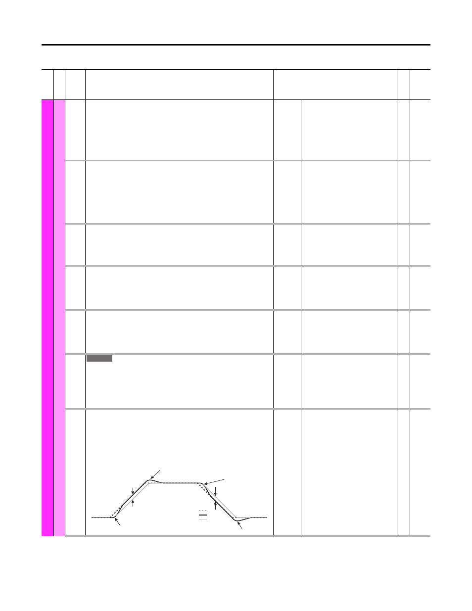
SpdReg AntiBckup
Speed Regulator Anti-backup
Allows control of over-shoot/under-shoot in the step response of the Vector control
mode speed regulator. Over-shoot/under-shoot can be effectively eliminated with a
setting of 0.3, which will remove backup of the motor shaft when zero speed is reached.
This parameter has no affect on the drive’s response to load changes. A value of zero
disables this feature.
Default:
Min/Max:
0.0000
0.0000 / 0.5000
RW Real
Fi
le
Grou
p
No.
Display Name
Full Name
Description
Values
Re
ad
-W
ri
te
Da
ta
T
ype
755
Under-Shoot
Over-Shoot
Over-Shoot
Under-Shoot
Error
Reference
Feedback, SpdReg AntiBckup = 0.0
Feedback, SpdReg AntiBckup = 0.3
Error