Process control (2), Figure 22 - process control (2) – Rockwell Automation 21G PowerFlex 750-Series AC Drives Programming Manual User Manual
Page 386
386
Rockwell Automation Publication 750-PM001J-EN-P - October 2014
Appendix A
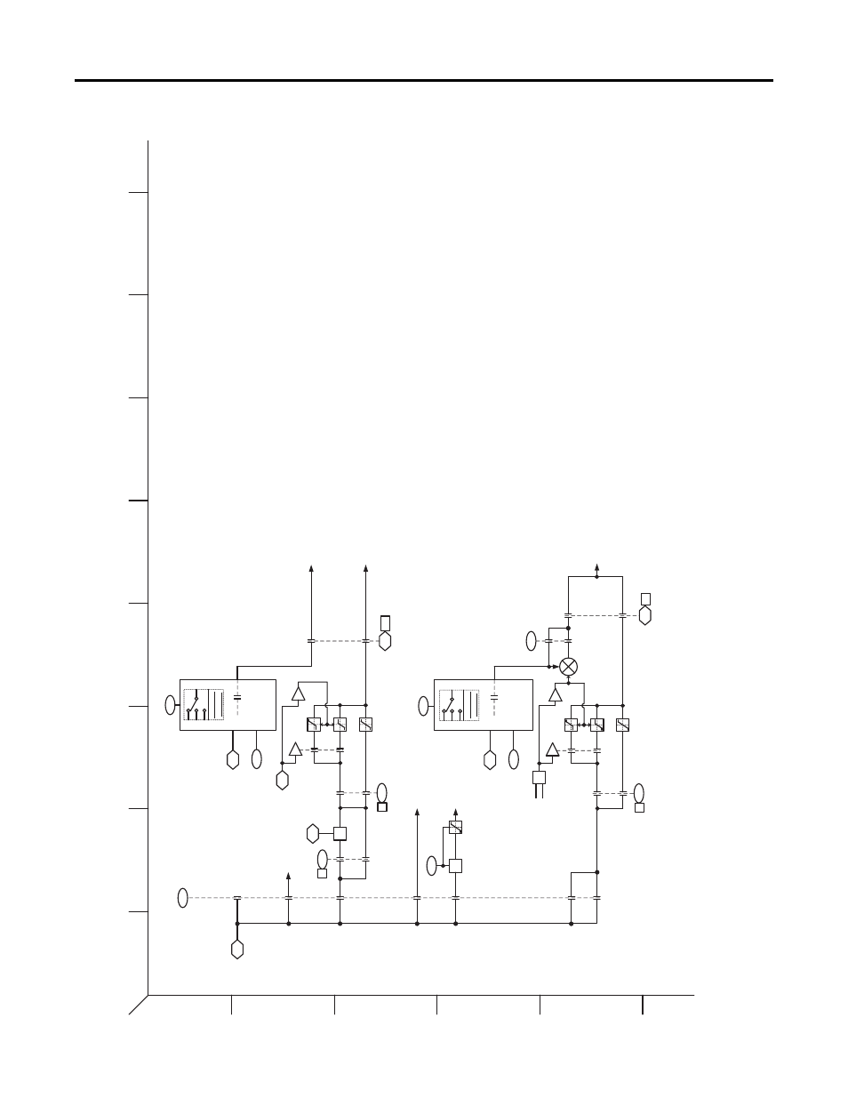
PowerFlex 753 Control Block Diagrams
Figure 22 - Process Control (2)
1
2
3
4
5
6
B
A
D
C
F
E
H
G
I
1093
PID O
utput
Me
te
r
1079
X
Limit
ed
Sp
d Ref
1065
6
PID
Cfg
(Perce
nt Ref)
1
0
1065
2
PI
D Cfg
(Z
ero Cl
amp)
>0
Ram
ped Spd
Ref
0
1
1
0
Ne
g Limit
Po
s Limit
-1
107
5
54
6
De
fault
Float T
ypes
M
OP Re
ference
558
1
0
PI
D FBL
oss SpS
el
Sp
d Ref A
Stpt
593
594
1065
2
PI
D Cfg
(Z
ero Cl
amp)
>0
T
orq Ref
A
0
1
1
0
Ne
g Limit
Pos L
imit
-1
+
+
676
Default
Floa
t Types
MO
P Refe
rence
55
8
3
1
4
0
Trq Re
f A Stp
t
T
orq Ref
B
+
107
9
PID O
utput S
el
P
ID Outp
ut Sel
0
1
2
5
6
3
4
107
6
PID
FBLo
ss TqS
el
X
PI
D Volta
ge Trim
Outpu
t
36
Maxi
mum V
oltage
PID
Voltag
e Outpu
t
936
10
Driv
e Status
2
(PID FB
Los
s)
936
10
Drive Status
2
(PID F
B
Loss)
Process Control (2)
Param
eter
Sele
ction
Par
ameter
Se
lection
[21F
2]
[21F2]
[19I
2]
Not
Us
ed
S
peed
Excl
Speed
Trim
Volt
Ex
cl
S
peed
Excl
Volt
Tr
im
Torque
Ex
cl
Tor
que
Trim
To Spd
Ref
[6B2]
[7G1] OR
[8G
2]
[6H
4]
To
Spd Re
f (Trim
)
[7B
5], [8A5]
To T
orq Ref
[16G4
]
[19C
4]
[19C
4]
To Spd
Re
f
[6B
2]
PF753
Rev_10.
a
Page 2
0