Rockwell Automation 21G PowerFlex 750-Series AC Drives Programming Manual User Manual
Page 188
188
Rockwell Automation Publication 750-PM001J-EN-P - October 2014
Chapter 3
Drive Port 0 Parameters
APPLIC
AT
IONS
Pr
of
ili
n
g
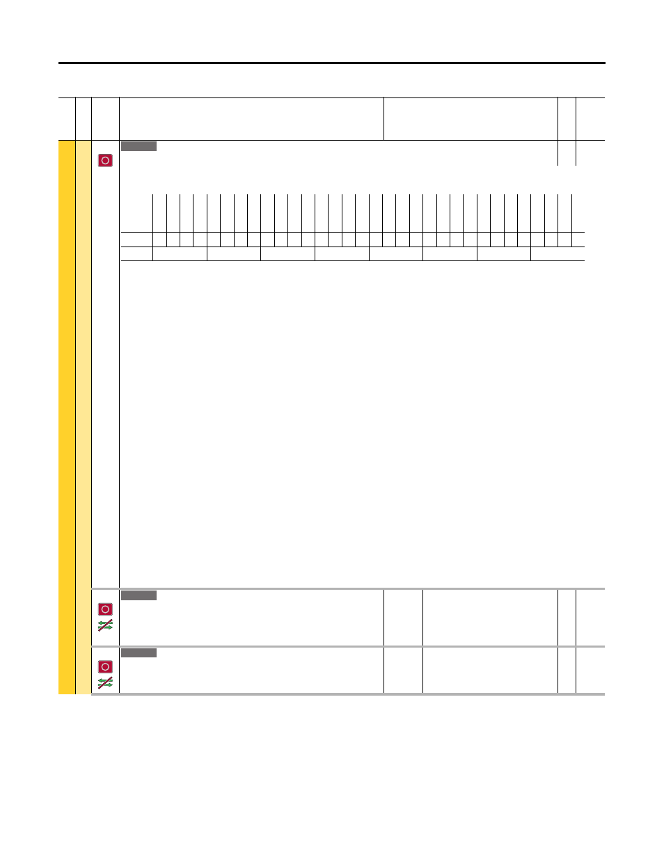
1217
Prof DI Invert
Profile Digital Input Invert
RW 32-bit
Integer
Sets polarity of the digital inputs. Each bit is assigned to a move table step. Rising edge of the digital input is used when the bit is off, and falling edge of digital
input is used when the bit is on.
Bit 0 “Hold Step” – sets polarity of the digital input for the hold step, P1218 [DI Hold Step].
Bit 1 “Abort Step” – sets polarity of the digital input for abort step, P1219 [DI Abort Step].
Bit 2 “AbortProfile” – sets polarity of the digital input for abort profile, P1220 [DI Abort Profile].
Bit 3 “Vel Override” – sets polarity of the digital input for velocity override, P1221 [DI Vel Override].
Bit 4 “StrStepSel0” – sets polarity of the digital input for start step 1, P1222 [DI StrtStep Sel0].
Bit 5 “StrStepSel1” – sets polarity of the digital input for start step 2, P1223 [DI StrtStep Sel1].
Bit 6 “StrStepSel2” – sets polarity of the digital input for start step 3, P1224 [DI StrtStep Sel2].
Bit 7 “StrStepSel3” – sets polarity of the digital input for start step 4, P1225 [DI StrtStep Sel3].
Bit 8 “StrStepSel4” – sets polarity of the digital input for start step 5, P1226 [DI StrtStep Sel4]
Bit 9 “Step 1” – sets polarity of the digital input for move step 1, P1230 [Step 1 Type].
Bit 10 “Step 2” – sets polarity of the digital input for move step 2, P1240 [Step 2 Type].
Bit 11 “Step 3” – sets polarity of the digital input for move step 3, P1250 [Step 3 Type].
Bit 12 “Step 4” – sets polarity of the digital input for move step 4, P1260 [Step 4 Type].
Bit 13 “Step 5” – sets polarity of the digital input for move step 5, P1270 [Step 5 Type].
Bit 14 “Step 6” – sets polarity of the digital input for move step 6, P1280 [Step 6 Type].
Bit 15 “Step 7” – sets polarity of the digital input for move step 7, P1290 [Step 7 Type].
Bit 16 “Step 8” – sets polarity of the digital input for move step 8, P1300 [Step 8 Type].
Bit 17 “Step 9” – sets polarity of the digital input for move step 9, P1310 [Step 9 Type].
Bit 18 “Step 10” – sets polarity of the digital input for move step 10, P1320 [Step 10 Type].
Bit 19 “Step 11” – sets polarity of the digital input for move step 11, P1330 [Step 11 Type].
Bit 20 “Step 12” – sets polarity of the digital input for move step 12, P1340 [Step 12 Type].
Bit 21 “Step 13” – sets polarity of the digital input for move step 13, P1350 [Step 13 Type].
Bit 22 “Step 14” – sets polarity of the digital input for move step 14, P1360 [Step 14 Type].
Bit 23 “Step 15” – sets polarity of the digital input for move step 15, P1370 [Step 15 Type].
Bit 24 “Step 16” – sets polarity of the digital input for move step 16, P1380 [Step 16 Type].
1218
DI Hold Step
Digital Input Hold Step
Sets a digital input port for the hold step in profile/indexer control logic. The digital
input assigned by this parameter is equivalent to P1213 [Profile Command] Bit 8 “Hold
Step.” Polarity of active state is defined by P1217 [Prof DI Invert] Bit 0 “Hold Step.”
Default:
Min/Max:
0.00
0.00 / 159999.15
RW 32-bit
Integer
1219
DI Abort Step
Digital Input Abort Step
Sets a digital input port for the abort step in profile/indexer control logic. Polarity of
active state is defined by P1217 [Prof DI Invert] Bit 1 “Abort Step.”
Default:
Min/Max:
0.00
0.00 / 159999.15
RW 32-bit
Integer
Fi
le
Grou
p
No.
Display Name
Full Name
Description
Values
Re
ad
-W
ri
te
Da
ta
T
ype
755
Options
Res
er
ved
Res
er
ved
Res
er
ved
Res
er
ved
Res
er
ved
Res
er
ved
Res
er
ved
Ste
p 16
Ste
p 15
Ste
p 14
Ste
p 13
Ste
p 12
Ste
p 11
Ste
p 10
Ste
p 9
Ste
p 8
Ste
p 7
Ste
p 6
Ste
p 5
Ste
p 4
Ste
p 3
Ste
p 2
Ste
p 1
St
rS
tep
Se
l4
St
rS
tep
Se
l3
St
rS
tep
Se
l2
St
rS
tep
Se
l1
St
rS
tep
Se
l0
Ve
l O
ve
rr
id
e
Ab
or
tP
ro
fil
e
Ab
or
t S
tep
Ho
ld
Ste
p
Default
0
0
0
0
0
0
0
0
0
0
0
0
0
0
0
0
0
0
0
0
0
0
0
0
0
0
0
0
0
0
0
0
Bit
31 30 29 28 27 26 25 24 23 22 21 20 19 18 17 16 15 14 13 12 11 10 9
8
7
6
5
4
3
2
1
0
0 = Condition False
1 = Condition True
755
755