Rockwell Automation 21G PowerFlex 750-Series AC Drives Programming Manual User Manual
Page 149
Rockwell Automation Publication 750-PM001J-EN-P - October 2014
149
Drive Port 0 Parameters
Chapter 3
CO
MMUNIC
AT
ION
Comm C
ontr
ol
871
872
873
874
875
876
877
878
Port 1 Reference
Port 2 Reference
Port 3 Reference
Port 4 Reference
Port 5 Reference
Port 6 Reference
Port13 Reference
Port14 Reference
Port n Reference
Reference value from port devices.
Units:
Default:
Min/Max:
Hz
RPM
0.00
–/+P27 [Motor NP Hertz] x 8
–/+P28 [Motor NP RPM] x 8
RO
Real
879
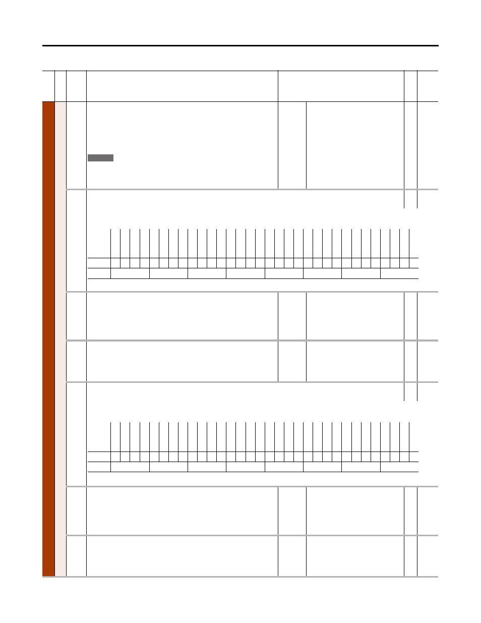
Drive Logic Rslt
Drive Logic Result
RO
32-bit
Integer
This is the logic output of the logic parser that combines the outputs from the DPI ports and the DeviceLogix controller to determine drive control based on the
masks and owners. Used for peer to peer communication with PowerFlex 750-Series communication modules.
880
DPI Ref Rslt
DPI Reference Result
Present speed reference scaled as a DPI reference for peer to peer communications. The
value shown is the value prior to the accel/decel ramp and the corrections supplied by
slip comp, PI, etc. Used for peer to peer communication with 20-COMM communication
modules.
Units:
Default:
Min/Max:
Hz
RPM
0.000
–2147483.648 / 2147483.624
RO
32-bit
Integer
881
DPI Ramp Rslt
DPI Ramp Result
Displays the speed reference value, after the limit function. This is the input to the error
calculator and speed regulator. Used for peer-to-peer communication with 20-COMM
communication modules.
Units:
Default:
Min/Max:
Hz
RPM
0.000
–2147483.648 / 2147483.624
RO
32-bit
Integer
882
DPI Logic Rslt
DPI Logic Result
RO
32-bit
Integer
A version of P879 that is used when doing peer-to-peer control with a 20-COMM communication module. The lower 16 bit command values are copied into the
upper 16 bits of this 32-bit parameter for use with this type of communication module. Not for use with a 20-750 communication module.
883
Drive Ref Rslt
Drive Reference Result
Present frequency reference scaled as a DPI reference for peer to peer communications.
The value shown is the value prior to the accel/decel ramp and the corrections supplied
by slip comp, PI, etc. Used for peer to peer communication with 20-COMM
communication modules.
Units:
Default:
Min/Max:
Hz
RPM
0.000
–/+2147483648.000
RO
32-bit
Integer
884
Drive Ramp Rslt
Drive Ramp Result
Displays the speed reference value, after the limit function. This is the input to the error
calculator and speed regulator. This number is scaled so that rated motor speed will read
32768. Used for peer to peer communication with 20-COMM communication modules.
Units:
Default:
Min/Max:
Hz
RPM
0.000
–/+2147483648.000
RO
32-bit
Integer
Fi
le
Grou
p
No.
Display Name
Full Name
Description
Values
Re
ad
-W
ri
te
Da
ta
T
ype
755
Options
Re
ser
ve
d
Re
ser
ve
d
Re
ser
ve
d
Re
ser
ve
d
Re
ser
ve
d
Re
ser
ve
d
Re
ser
ve
d
Re
ser
ve
d
Re
ser
ve
d
Re
ser
ve
d
Re
ser
ve
d
Re
ser
ve
d
Jog 2
Run
Cl
im
it S
top
Co
as
t S
to
p
Re
ser
ve
d
SpdRef Sel
2
SpdRef Sel
1
SpdRef Sel
0
D
ecel T
ime
2
D
ecel T
ime
1
Acce
l T
im
e 2
Acce
l T
im
e 1
Re
ser
ve
d
Manual
Re
ve
rse
Fo
rw
ar
d
Cl
ea
r F
au
lts
Jog 1
St
ar
t
Sto
p
Default
0
0
0
0
0
0
0
0
0
0
0
0
0
0
0
0
0
0
0
0
0
0
0
0
0
0
0
0
0
0
0
0
Bit
31 30 29 28 27 26 25 24 23 22 21 20 19 18 17 16 15 14 13 12 11 10 9
8
7
6
5
4
3
2
1
0
0 = False, 1 = True
Options
Re
se
rv
ed
Spd
Re
f Se
l 2
Spd
Re
f Se
l 1
Spd
Re
f Se
l 0
D
ecel T
ime 2
D
ecel T
ime 1
Ac
cel T
ime
2
Ac
cel T
ime
1
Re
se
rv
ed
Manual
Re
ve
rs
e
Fo
rw
ar
d
Clear F
aults
Jog 1
Star
t
St
op
Re
se
rv
ed
Spd
Re
f Se
l 2
Spd
Re
f Se
l 1
Spd
Re
f Se
l 0
D
ecel T
ime 2
D
ecel T
ime 1
Ac
cel T
ime
2
Ac
cel T
ime
1
Re
se
rv
ed
Manual
Re
ve
rs
e
Fo
rw
ar
d
Clear F
aults
Jog 1
Star
t
St
op
Default
0
0
0
0
0
0
0
0
0
0
0
0
0
0
0
0
0
0
0
0
0
0
0
0
0
0
0
0
0
0
0
0
Bit
31 30 29 28 27 26 25 24 23 22 21 20 19 18 17 16 15 14 13 12 11 10 9
8
7
6
5
4
3
2
1
0
0 = False, 1 = True