Program examples, Example 1: selector switch operation – Rockwell Automation 21G PowerFlex 750-Series AC Drives Programming Manual User Manual
Page 490
490
Rockwell Automation Publication 750-PM001J-EN-P - October 2014
Appendix C
Using DeviceLogix
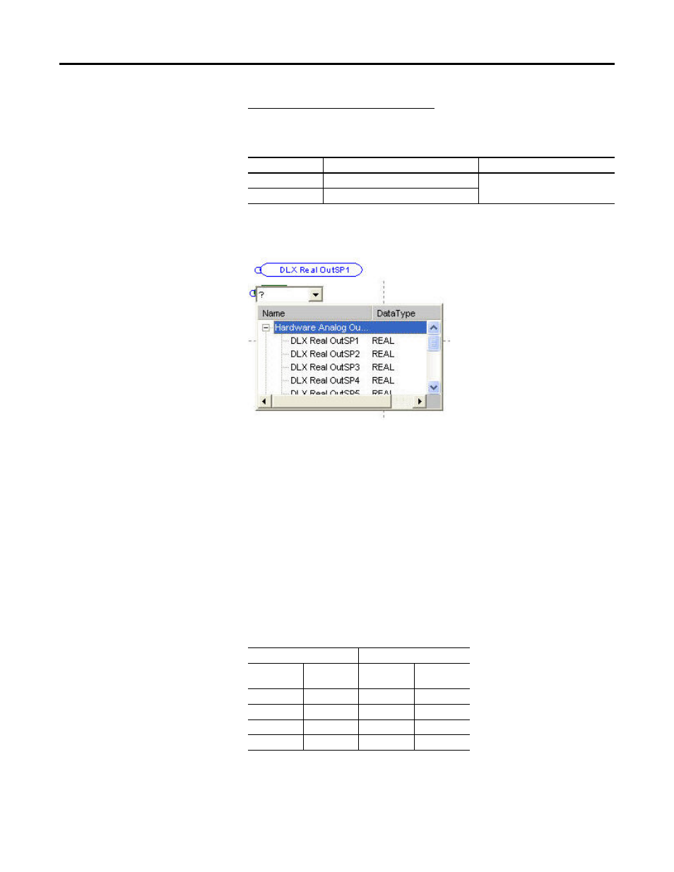
Example 2 – Writing data to the network
The DeviceLogix program controls an Analog Output value which is written to
DLX Real OutSP1.
DLX Real OutSP1 can now be used as a Hardware Analog Output and used
directly with a Function Block (a DeviceLogix Datalink is not required).
Program Examples
Example 1: Selector Switch Operation
This example demonstrates how a selector switch operation similar to the feature
in the PowerFlex 700S can be achieved through the embedded DeviceLogix in
the PowerFlex 750-Series drive. A selector switch is simulated in the drive using a
combination of inputs to produce multiple outputs. Digital inputs in the drive
are used to output configurable multiple preset speeds (75 Hz, 85Hz, 95Hz, and
105Hz) to P571 [Preset Speed 1]. It is assumed that the 750-Series drive has an I/
O module that is installed in Port 4.
The following truth table represents the inputs and outputs for a 4 position
selector switch.
The Logic Map offers a high level explanation of how the above outputs are
achieved.
Drive
Datalink
Value
753
Port 0 P905 [Data Out A1]
Port 14: DLX Real OutSP1
755
Port 13 P17 [DL To Net 01]
Inputs
Outputs
Input 1
Input 2
Binary Output
Selector Switch
Output
0
0
0
Output A
0
1
1
Output B
1
0
2
Output C
1
1
3
Output D