Universal feedback module parameters – Rockwell Automation 21G PowerFlex 750-Series AC Drives Programming Manual User Manual
Page 274
274
Rockwell Automation Publication 750-PM001J-EN-P - October 2014
Chapter 5
Embedded Feature and Option Module Parameters
Universal Feedback Module
Parameters
Fil
e
Gr
oup
No.
Display Name
Full Name
Description
Values
Re
ad
-Write
Da
ta
T
yp
e
U
n
iv
er
sal
F
eed
ba
ck
Mo
dule
1
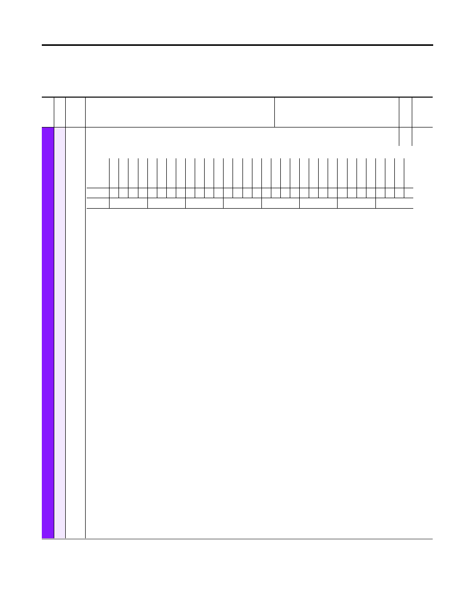
Module Sts
Module Status
RO
16-bit
Integer
Shows error and alarm information of the Feedback Option module.
Bit 0 “Module Error” – Indicates that the Feedback Option module has any error. This bit is set if at least one of the bits “FB0 Error”, “FB1 Error”, or “System Error” is
set.
Bit 1 “Alarm Type 1” – Indicates that there is any alarm of type 1 active on the Feedback Option module. Bits 8…10 indicate what kind of alarm is active.
Bit 2 “Alarm Type 2” – Indicates that there is any alarm of type 2 active on the Feedback Option module. Bits 20 and 21 indicate what kind of alarm is active.
Bit 4 “FB0 Error” – Indicates that Feedback 0 has an error. This bit is set if any Feedback 0 error bit in P10 [FB0 Sts] is set. If this bit is set, Bit 0 “Module Error” is also
set.
Bit 5 “FB1 Error” – Indicates that Feedback 1 has an error. This bit is set if any Feedback 1 error bit in P10 [FB1 Sts] is set. If this bit is set, Bit 0 “Module Error” is also
set.
Bit 6 “System Error” – Indicates that there is a feedback independent error on the Feedback Option module. Bits 12 and 13 show the type of the System Error. If this
bit is set, Bit 0 “Module Error” is also set.
Bit 8 “FB0 Alarm” – Indicates that feedback device 0 has an alarm. This bit is set if there is an alarm in the Feedback 0 encoder. If this bit is set, Bit 1 “Alarm Type 1”
and P10 [FB0 Sts] Bit 12 “Encoder Alm” will also be set. The specific alarm condition may be shown in a status found under the diagnostics tab for the Universal
Feedback Module. Separate diagnostic items are provided for both ports and for both of the following devices: EnDat and BiSS. Alarm conditions for Linear Stahl
feedback devices can be found in P27 [FB0 LinStahl Sts] and P57 [FB1 LinStahl Sts].
Bit 9 “FB1 Alarm” – Indicates that feedback device 1 has an alarm. This bit is set if there is an alarm in the Feedback 1 encoder. If this bit is set, Bit 1 “Alarm Type 1”
and P40 [FB1 Sts] Bit 12 “Encoder Alm” will also be set. The specific alarm condition may be shown in a status found under the diagnostics tab for the Universal
Feedback Module. Separate diagnostic items are provided for both ports and for both of the following devices: EnDat and BiSS. Alarm conditions for Linear Stahl
feedback devices can be found in P27 [FB0 LinStahl Sts] and P57 [FB1 LinStahl Sts].
Bit 10 “Cfg Alarm” – Indicates that there is a feedback independent alarm on the Feedback Option module. Bits 16 and 17 show the type of the Cfg Alarm. If this bit
is set, Bit 1 “Alarm Type 1” is also set.
Bit 12 “Hardware Err” – Indicates that there is a Hardware Error on the Feedback Option module. If this bit is set, Bit 6 “System Error” is also set. The hardware is self
tested by the board at powerup. Specific details of the hardware failure are not available.
Bit 13 “Firmware Err” – Indicates that there is a Firmware Error on the Feedback Option module. A Firmware Error occurs if the Hardware and the downloaded
Firmware are not compatible. If this bit is set, Bit 6 “System Error” is also set.
Bit 16 “EncOut Cflct” – If set, there is one of the following problems with the Encoder Output:
• The selection in P80 [Enc Out Sel] is not possible since the required pins on the terminal blocks are already used for Feedback 0 or 1 according to P6 [FB0 Device
Sel] and P36 [FB1 Device Sel].
• P80 [Enc Out Sel] is set to “Sine Cosine” and there is no signal connected to the pins 1-4 of the Terminal Block 1.
• P80 [Enc Out Sel] is set to “Sine Cosine”, the value of [FBn IncAndSC PPR] is not a power of two, and the parameter P84 [Enc Out Z PPR] is not set to 0 “1 ZPulse.”
This is not allowed.
• P80 [Enc Out Sel] is set to “Channel X” or “Channel Y” and there is no encoder connected to that channel.
• P80 [Enc Out Sel] is set to “Channel X” or “Channel Y” and there is a linear encoder connected to this channel. If this bit is set, Bit 10 “Cfg Alarm” is also set.
Bit 17 “Safety Cflct” – If set, the Safety DIP switches are in an invalid position. If this bit is set, Bit 10 “Cfg Alarm” is also set.
Bit 20 “FB0FB1 Cflct” – If set, the combination of the feedback selection done with the parameters P6 [FB0 Device Sel] and P36 [FB1 Device Sel] is invalid, i.e. both
feedbacks have Sin-Cos-Signals (There is only place for one set of Sin-Cos-Signals on the Terminal Blocks). If this bit is set, Bit 2 “Alarm Type 2” is also set.
Bit 21 “Initializing” – Indicates that the Universal Feedback State Machine is in the Initialize State. This Type 2 alarm makes sure that the motor cannot be started
during the initialization state. If this bit is set, Bit 2 “Alarm Type 2” is also set.
Bit 29 “Pri Safety” – Indicates that the UFB is used as primary safety module.
Bit 30 “Sec Safety” – Indicates that the UFB is used as secondary safety module.
Bit 31 “DPI Ready” – This bit tells the MCB if the UFB is ready for DPI communication.
Options
DPI Ready
Sec
Sa
fe
ty
Pri
S
afet
y
Re
se
rv
ed
Re
se
rv
ed
Re
se
rv
ed
Re
se
rv
ed
Re
se
rv
ed
Re
se
rv
ed
Re
se
rv
ed
In
itia
lizin
g
FB0FB1 Cflc
t
Re
se
rv
ed
Re
se
rv
ed
Sa
fe
ty
C
flc
t
Enc
O
ut Cflc
t
Re
se
rv
ed
Re
se
rv
ed
Fi
rm
wa
re
E
rr
H
ard
wa
re
E
rr
Re
se
rv
ed
Cfg Alarm
FB1 Ala
rm
FB0 Ala
rm
Re
se
rv
ed
Sy
st
em
Er
ro
r
FB1 Err
or
FB0 Err
or
Re
se
rv
ed
Alarm T
yp
e
2
Alarm T
yp
e
1
Modul
e Err
or
Default
0
0
0
0
0
0
0
0
0
0
0
0
0
0
0
0
0
0
0
0
0
0
0
0
0
0
0
0
0
0
0
0
Bit
31 30 29 28 27 26 25 24 23 22 21 20 19 18 17 16 15 14 13 12 11 10 9
8
7
6
5
4
3
2
1
0
0 = False
1 = True