13 synchronisation of the internal time base – Lenze 8400 StateLine User Manual
Page 576
13
Synchronisation of the internal time base
13.1
Internal interfaces | System block "LS_SyncManagement"
576
Lenze · 8400 StateLine · Reference manual · DMS 12.0 EN · 06/2014 · TD05/TD14
_ _ _ _ _ _ _ _ _ _ _ _ _ _ _ _ _ _ _ _ _ _ _ _ _ _ _ _ _ _ _ _ _ _ _ _ _ _ _ _ _ _ _ _ _ _ _ _ _ _ _ _ _ _ _ _ _ _ _ _ _ _ _ _
Sync phase position
The phase position determines the zero-time of the internal system cycle with regard to the
synchronisation signal (bus cycle). Since PDO processing is an inherent part of the system part of the
application, the instant of acceptance of the PDOs is postponed as well by a changed phase position.
• If "0" is set, the internal system cycle starts at the same time as the synchronisation signal.
• If a value > 0 is set, the internal system cycle starts by the set time earlier (the phase position has
a negative effect) than the synchronisation signal.
• Intelligent communication modules define the optimal time with activated synchronisation by
themselves. In this case, a manual change is not possible.
• For determining
, the point in time where all bus nodes have valid PDOs is decisive.
Example: If the phase position is set to 550 μs, the system part of the application starts 550 μs
before the arrival of the synchronisation signal.
Sync correction width
If the cycle times of the synchronisation signal and the phase-locking loop (PLL) are different, the
setting in
defines the correction increments for the phase-locking loop.
• The recommended reset time for the CAN bus as synchronisation source in case of occurring
deviations is 300 ns (Lenze setting).
• If synchronisation is not reached, select a higher correction width.
• The optimum setting depends on quartz precision and must be determined empirically if
required.
13.1
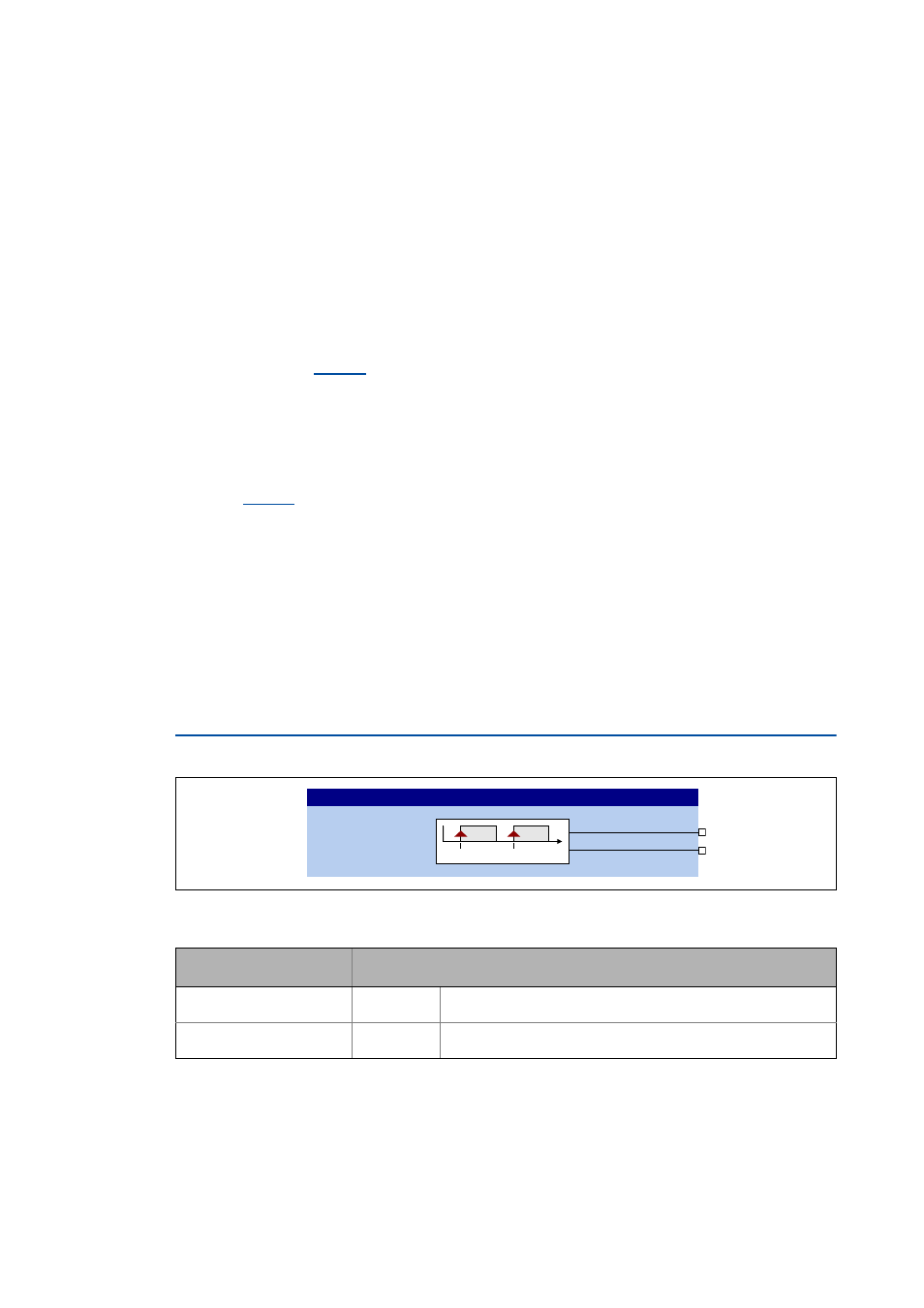
Internal interfaces | System block "LS_SyncManagement"
This function extension is available from version 11.00.00!
The SB LS_SyncManagement provides status information for synchronising the internal time base:
Outputs
Identifier
Data type
Value/meaning
bSyncSignalOK
BOOL
TRUE Sync signal OK
bSyncPhaseOK
BOOL
TRUE Sync phase position OK
/6B6\QF0DQDJHPHQW
E6\QF6LJQDO2.
E6\QF3KDVH2.
W
6<1&
6<1&