1 technical data, 10 oscilloscope function – Lenze 8400 StateLine User Manual
Page 473
Lenze · 8400 StateLine · Reference manual · DMS 12.0 EN · 06/2014 · TD05/TD14
473
10
Oscilloscope function
10.1
Technical data
_ _ _ _ _ _ _ _ _ _ _ _ _ _ _ _ _ _ _ _ _ _ _ _ _ _ _ _ _ _ _ _ _ _ _ _ _ _ _ _ _ _ _ _ _ _ _ _ _ _ _ _ _ _ _ _ _ _ _ _ _ _ _ _
Functional description
In the »Engineer«, you set the trigger condition and sample rate and select the variables to be
recorded via the oscilloscope user interface when an online connection to the 8400 StateLine has
been established. In this case, "variables" are the internal output signals of the function, system,
application and port blocks.
Every configuration change is transferred to the 8400 StateLine and checked. If invalid settings are
found, the oscilloscope triggers an error.
With an online connection, the measured 8400 StateLine data are transferred to the »Engineer« and
graphically represented on the oscilloscope user interface as soon as the measurement has been
completed.
10.1
Technical data
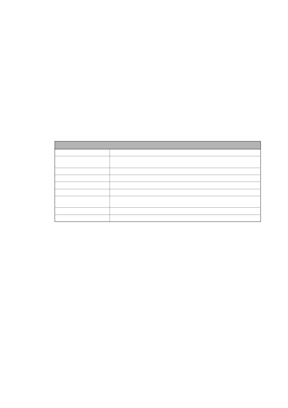
Oscilloscope function of 8400 StateLine
Number of channels
1 ... 4
Memory depth
Max. 8192 measured values, depending on the number of channels and the size of
the variables to be recorded
Data width of a channel
Max. 32 bits, corresponding to the data type of the variable to be recorded
Sample rate
1 ms or a multiple thereof
Time base
5, 10, 20, 50, 100, 200, 500 ms or 1 s
Trigger level
Corresponding to the value range of the variable to be triggered
Trigger selection
The trigger is activated if the trigger value set for the respective channel is fallen
short of or exceeded. The trigger value "must actually pass" the threshold.
Trigger delay
-100 % ... +400 %
Trigger source
Channel 1 ... 4