5motor control (mctrl), Stop – Lenze 8400 StateLine User Manual
Page 115
Lenze · 8400 StateLine · Reference manual · DMS 12.0 EN · 06/2014 · TD05/TD14
115
5
Motor control (MCTRL)
5.1
Motor selection/Motor data
_ _ _ _ _ _ _ _ _ _ _ _ _ _ _ _ _ _ _ _ _ _ _ _ _ _ _ _ _ _ _ _ _ _ _ _ _ _ _ _ _ _ _ _ _ _ _ _ _ _ _ _ _ _ _ _ _ _ _ _ _ _ _ _
• The available motor cable must be specified in terms of length and cross-section:
The motor cable resistance resulting from these settings is displayed in
.
• For the measurement of the required variables, the motor is energised via the controller
terminals U, V and W during the motor parameter identification. The corresponding current
controller is preset in the Lenze setting so that a optimal controller behaviour is achieved with
an asynchronous motor power-adapted to the controller.
Thanks to optimisation, the current controller can be set via the following parameters:
• Switching frequency for the motor parameter identification:
•
Up to and including version 13.xx.xx
, the motor parameter identification is executed with a
switching frequency of 4 kHz.
•
From version 14.00.00
, the motor parameter identification can also be executed with a
switching frequency of 8 kHz instead of 4 kHz. For this purpose, the option "Motor ident.:
Switching frequency 8 kHz" (Bit 4 = "1") has to be set in
.
Example of how to use this option: Between the output of the inverter and the motor, a
sinusoidal filter is connected which may only be operated with a minimum switching
frequency of 8 kHz. (See also the section "
Preventing a decrease of the switching frequency
".)
( 203)
Generally, a switching frequency of 4 kHz is recommended for the motor parameter
identification as it serves to obtain the most accurate results.
Premature abort of the motor parameter identification
The motor parameter identification can be aborted in the following cases:
• If a special motor (e.g. mid-frequency motor) or a servo motor is used.
• If there is a large deviation between inverter and motor power.
In case of a simple motor parameter identification, we recommend the following:
• to reduce the P component Vp of the current controller (
) e.g. by halving.
• to increase the time constant Ti of the current controller (
) e.g. by doubling.
In case of the extended motor parameter identification, the current controller parameters are
determined automatically. If the identification is aborted all the same, the current controller
parameters set in
and
to "1".
Another cause for the abort of the motor parameter identification could be the implausibility of the
entered nameplate data, e.g. the entry P = 0 kW for the motor power.
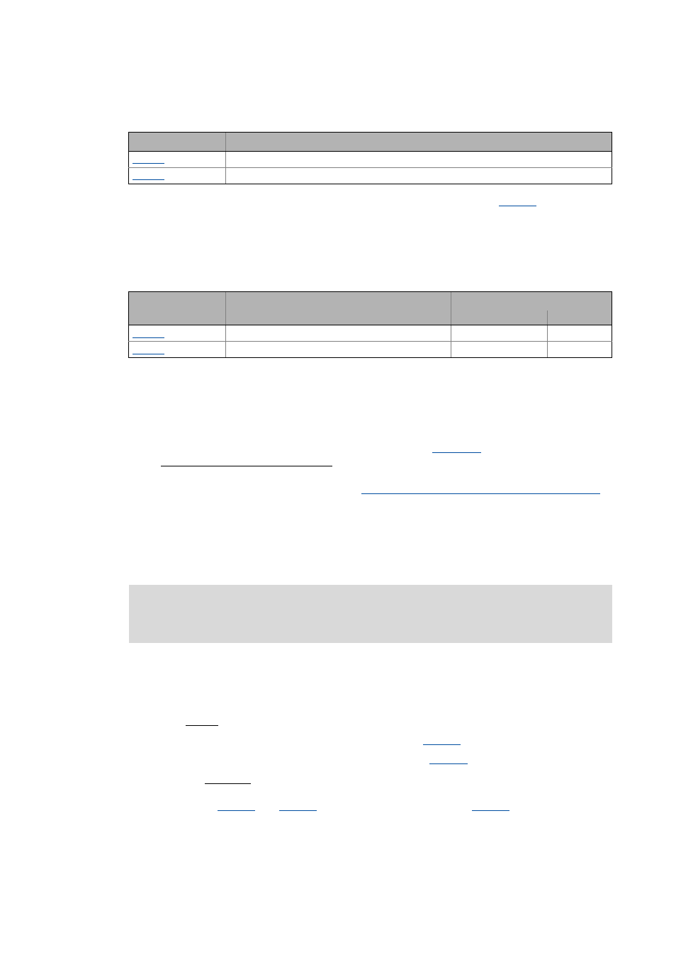
Parameter
Info
Motor cable length
Motor cable cross-section
Parameter
Info
Lenze setting
Value Unit
Vp current controller
7.00 V/A
Ti current controller
10.61 ms
Stop!
If motor parameter identification is aborted, unstable drive behaviour may be the result!