6 structure of the can data telegram, 1 identifier, Identifier – Lenze 8400 StateLine User Manual
Page 496: 11 system bus "can on board
11
System bus "CAN on board"
11.6
Structure of the CAN data telegram
496
Lenze · 8400 StateLine · Reference manual · DMS 12.0 EN · 06/2014 · TD05/TD14
_ _ _ _ _ _ _ _ _ _ _ _ _ _ _ _ _ _ _ _ _ _ _ _ _ _ _ _ _ _ _ _ _ _ _ _ _ _ _ _ _ _ _ _ _ _ _ _ _ _ _ _ _ _ _ _ _ _ _ _ _ _ _ _
11.6
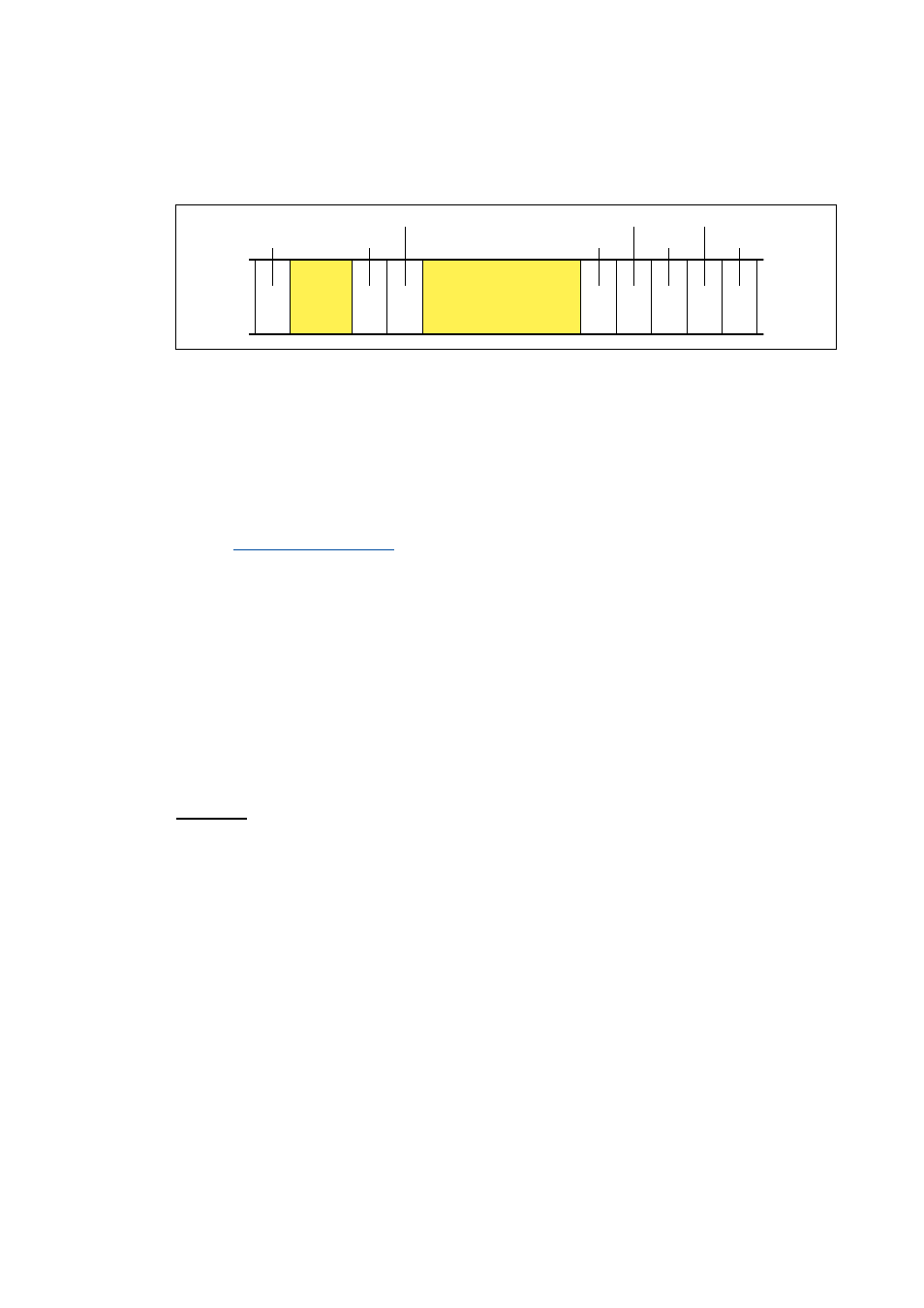
Structure of the CAN data telegram
[11-2] Basic structure of the CAN telegram
The following subchapters provide a detailed description of the identifier and the user data. The
other signals refer to the transfer characteristics of the CAN telegram whose description is not
included in the scope of this documentation.
Tip!
Please visit the homepage of the CAN user organisation CiA (CAN in automation) for further
information:
11.6.1
Identifier
The principle of the CAN communication is based on a message-oriented data exchange between a
transmitter and many receivers. All nodes can transmit and receive quasi-simultaneously.
The identifier, also called COB-ID (abbr. for communication object identifier), is used to control
which node is to receive a transmitted message. In addition to the addressing, the identifier
contains information on the priority of the message and the type of user data.
The identifier consists of a basic identifier and the node address of the node to be addressed:
Identifier (COB-ID) = basic identifier + node address (node ID)
Exception: The identifier for process data/heartbeat/emergency objects as well as network
management and sync telegrams is freely assigned by the user (either manually or automatically by
the network configurator), or is permanently assigned.
%LW
%LW
%LW
%LW
%LW
%LW
%LW
%LW
%LW
6WDUW
575ELW
&RQWUROILHOG
&5&VHTXHQFH
&5&GHOLPLWHU
$&.GHOLPLWHU
$&.VORW
(QG
,GHQWLILHU
8VHUGDWD%\WH
1HWZRUNPDQDJHPHQW
3URFHVVGDWD
3DUDPHWHUGDWD