2 analog terminals, Analog terminals, 6i/o terminals – Lenze 8400 StateLine User Manual
Page 280
6
I/O terminals
6.2
Analog terminals
280
Lenze · 8400 StateLine · Reference manual · DMS 12.0 EN · 06/2014 · TD05/TD14
_ _ _ _ _ _ _ _ _ _ _ _ _ _ _ _ _ _ _ _ _ _ _ _ _ _ _ _ _ _ _ _ _ _ _ _ _ _ _ _ _ _ _ _ _ _ _ _ _ _ _ _ _ _ _ _ _ _ _ _ _ _ _ _
6.2
Analog terminals
The analog input terminals together with the analog output terminals are located on the X3 plug
connector.
Analog input terminals
The drive controller has two analog input terminals for detecting one current signal and one voltage
signal:
• Voltage signal in the ± 10 V range
The voltage signal can be e.g. an analog speed setpoint or the signal of an external sensor
(temperature, pressure, etc.).
• Current signal in the 0/+ 4 ... + 20 mA range
For open-circuit monitoring, the current signal can be evaluated with regard to "Life Zero" or
"Dead Zero":
• 0 ... 20 mA, without open-circuit monitoring
• 4 ... 20 mA, with open-circuit monitoring
Analog output terminal
The controller has an analog output terminal for outputting an analog voltage signal (O1U).
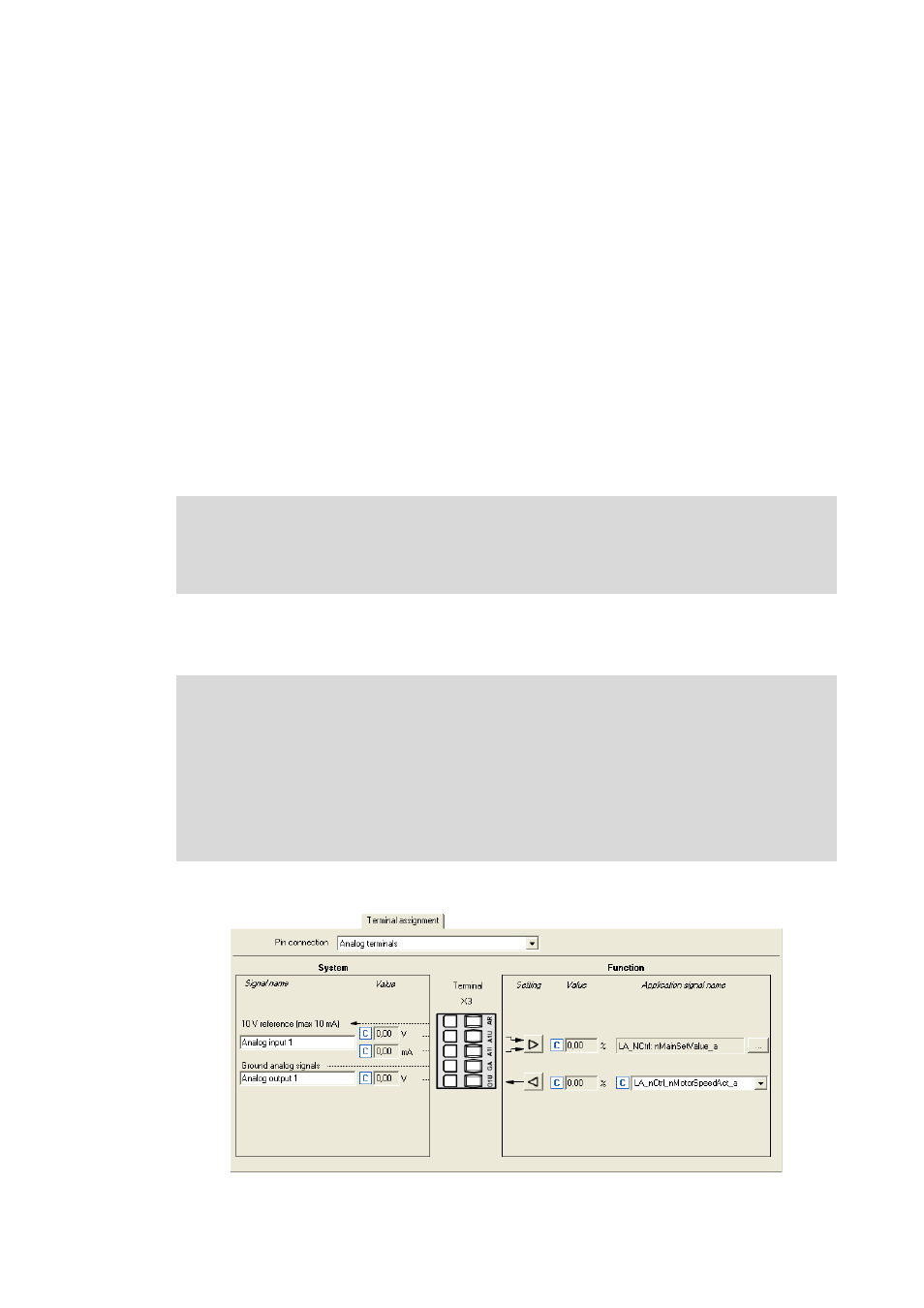
Parameterisation dialog in the »Engineer«:
Note!
To avoid undefined states, free input terminals of the controller must be assigned as
well, e.g. by applying 0 V to the terminal.
Note!
Initialisation behaviour:
• After mains switching up to the start of the application, the analog output remains
set to 0 V.
Exception handling:
• In case of a critical exception in the application (e.g. reset), the analog output is set to
0 V.