Oc6: i2xt motor overload, Oc6: i2xt overload motor, Error message – Lenze 8400 StateLine User Manual
Page 461: Lp1: motor phase failure, Sd3: open circuit - feedback system, Xx.0125.00001, Xx.0123.00145, Xx.0123.00105, Xx.0123.00205, Xx.0123.00200
Lenze · 8400 StateLine · Reference manual · DMS 12.0 EN · 06/2014 · TD05/TD14
461
9
Diagnostics & error management
9.9
Error messages of the operating system
_ _ _ _ _ _ _ _ _ _ _ _ _ _ _ _ _ _ _ _ _ _ _ _ _ _ _ _ _ _ _ _ _ _ _ _ _ _ _ _ _ _ _ _ _ _ _ _ _ _ _ _ _ _ _ _ _ _ _ _ _ _ _ _
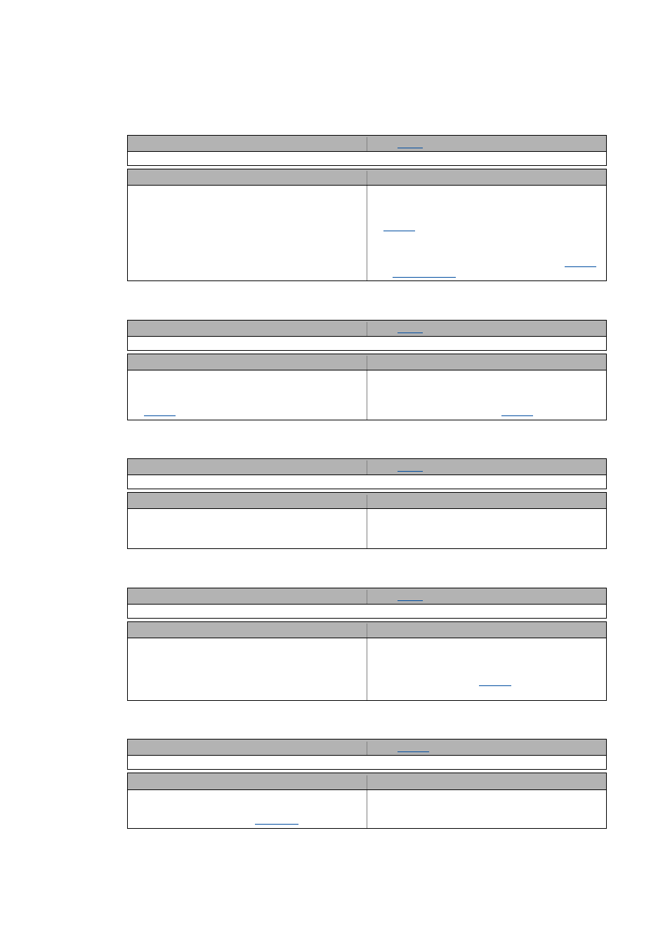
oC6: I2xt overload - motor [xx.0123.00105]
LP1: Motor phase failure [xx.0123.00145]
Sd10: Speed limit - feedback system 12 [xx.0123.00200]
Sd3: Open circuit - feedback system [xx.0123.00205]
An01: AIN1_I < 4 mA [xx.0125.00001]
Response (Lenze setting printed in bold)
Setting:
( Adjustable response)
0: No Reaction 1: Fault 2: Trouble 3: TroubleQuickStop 4: WarningLocked 5: Warning 6: Information
Cause
Remedy
Thermal overload of the motor.
Only self-ventilated motors can be monitored using the
I2xt function.
• Check whether is it a self-ventilated motor. If not, set
to "0: No Reaction".
• Observe load requirements.
• Correct dimensioning if necessary.
• For VFCplus control type: Check Vmin boost (
).
Response (Lenze setting printed in bold)
Setting:
( Adjustable response)
0: No Reaction 1: Fault 2: Trouble 3: TroubleQuickStop 4: WarningLocked 5: Warning 6: Information
Cause
Remedy
Motor phase failure - power section
• This error message is displayed if a motor phase
carries less current of one half-wave than set in
.
• Check the motor connections and the corresponding
plug connector on the device and, if necessary, the
motor terminal box.
• Check the trigger threshold (
).
Response (Lenze setting printed in bold)
Setting:
( Adjustable response)
0: No Reaction 1: Fault 2: Trouble 3: TroubleQuickStop 4: WarningLocked 5: Warning 6: Information
Cause
Remedy
Maximally permissible speed of the feedback system
connected to DI1/DI2 reached.
Reduce speed of the rotation shaft/feedback system.
n
encoder
<= (f
max
x 60) / encoder increments
(for f
max
= 10 kHz)
Response (Lenze setting printed in bold)
Setting:
( Adjustable response)
0: No Reaction 1: Fault 2: Trouble 3: TroubleQuickStop 4: WarningLocked 5: Warning 6: Information
Cause
Remedy
• HTL encoder cable interrupted.
• HTL encoder is defective.
Note: May also be caused by a very dynamic acceleration
or starting up against a blocked motor shaft (e.g. with a
closed holding brake).
• Check HTL encoder cable.
• Check HTL encoder.
• Check related terminals.
• Switch off monitoring (
= "0: No reaction")
when the HTL encoder is not used.
Response (Lenze setting printed in bold)
Setting:
( Adjustable response)
0: No Reaction 1: Fault 2: Trouble 3: TroubleQuickStop 4: WarningLocked 5: Warning 6: Information
Cause
Remedy
Open-circuit monitoring for analog input 1 has tripped.
• Only if the analog input has been configured as a
current loop of 4 ... 20 mA (
= 2).
• Check wiring of the analog X3/A1I input terminal for
open circuit.
• Check minimum current values of the signal sources.