1 parameterising digital inputs as encoder inputs, Parameterising digital inputs as encoder inputs, 5motor control (mctrl) – Lenze 8400 StateLine User Manual
Page 222: Danger
5
Motor control (MCTRL)
5.10
Encoder/feedback system
222
Lenze · 8400 StateLine · Reference manual · DMS 12.0 EN · 06/2014 · TD05/TD14
_ _ _ _ _ _ _ _ _ _ _ _ _ _ _ _ _ _ _ _ _ _ _ _ _ _ _ _ _ _ _ _ _ _ _ _ _ _ _ _ _ _ _ _ _ _ _ _ _ _ _ _ _ _ _ _ _ _ _ _ _ _ _ _
General procedure
(if the encoder is connected to the digital inputs DI1 and DI2)
1. Define the function of the digital inputs DI1 and DI2 in
.
2. Set the encoder increments in
3. Select "1: Encoder signal FreqIn12" in
4. Adapt the filter time of the speed measurement in
5.10.1
Parameterising digital inputs as encoder inputs
Define the function of the digital inputs DI1 and DI2 in
To be able to use the digital inputs as encoder inputs, select 2, 3, or 4 (Lenze recommendation: 2) in
depending on the input terminals used.
Related topics:
Using DI1 and DI2 as frequency inputs
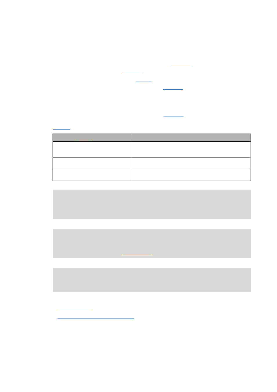
Selection in
Function
2: (DI1/DI2)=FreqIn12 (2-track)
DI1 and DI2 = 2-track frequency input
• Permits a two-track evaluation of the encoder including correct
detection of the direction of rotation.
3: (DI1/DI2=+-)=FreqIn12
DI1 = 1-track frequency input
DI2 = specification of direction
4: DI1=CountIn1 | DI2=In2
DI1 = counter input
DI2 = digital input
Danger!
For single-track evaluation, make sure that the sign is correctly specified. Otherwise, the
motor may overspeed.
Note!
If the digital inputs are parameterised as encoder inputs, the corresponding output
signals (bIn1/bIn2) at the
system block are automatically set to FALSE.
The wiring diagram and assignment of the input terminals are described in the 8400
hardware manual . The hardware manual has been stored in electronic form on the data
carrier supplied with the 8400 controller.