10 encoder/feedback system, Encoder/feedback system, Ailable – Lenze 8400 StateLine User Manual
Page 220: Encoder/feedback system ( 220), 5motor control (mctrl), Danger
5
Motor control (MCTRL)
5.10
Encoder/feedback system
220
Lenze · 8400 StateLine · Reference manual · DMS 12.0 EN · 06/2014 · TD05/TD14
_ _ _ _ _ _ _ _ _ _ _ _ _ _ _ _ _ _ _ _ _ _ _ _ _ _ _ _ _ _ _ _ _ _ _ _ _ _ _ _ _ _ _ _ _ _ _ _ _ _ _ _ _ _ _ _ _ _ _ _ _ _ _ _
5.10
Encoder/feedback system
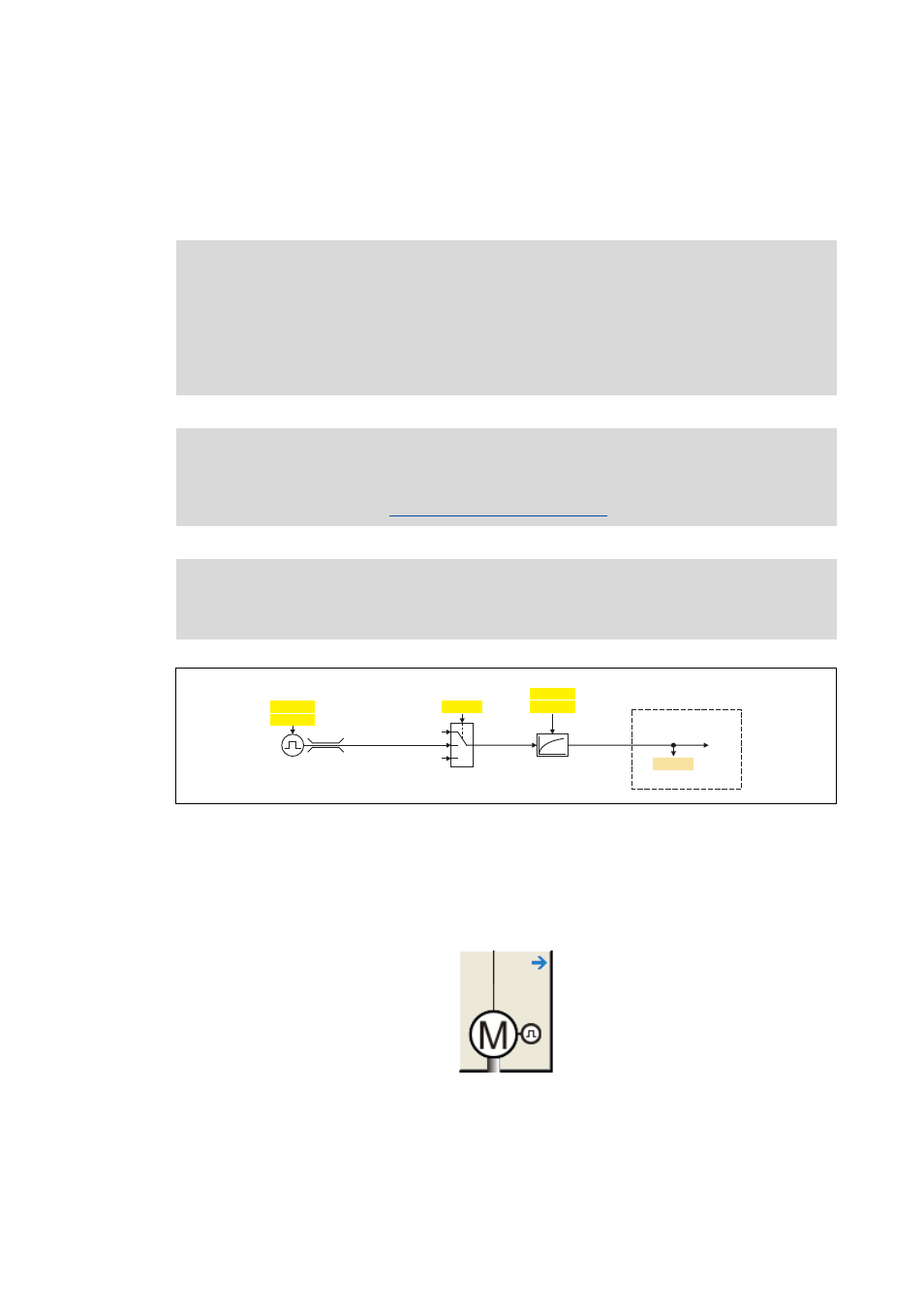
For motor control with speed feedback, the feedback signal can be fed to the digital terminals
(DI1/DI2) via an HTL encoder.
[5-24] Signal flow - encoder interface
How to get to the parameterisation dialog of the encoder/feedback system:
1. »Engineer« Go to the Project view and select the 8400 StateLine controller.
2. Select the Application parameters tab from the Workspace.
3. Go to the Overview dialog level and click the following button:
4. Go to the Overview Motor data dialog level and click the Encoder/Feedback system...
button.
Danger!
• To avoid interference when using an encoder, only use shielded motor and encoder
cables.
• If an HTL encoder is used at the digital input terminals:
Observe the maximum input frequencies of the digital inputs!
• DI1/DI2: max. 10 kHz
Note!
In the Lenze setting (e.g. when the device is delivered), the open-circuit monitoring of the
encoder is activated.
Encoder open-circuit monitoring
Wiring diagram, assignment and electrical data of the digital input terminals can be
found in the hardware manual 8400 in the chapter "technical data". The hardware
manual is stored in electronic form on the data carrier supplied with the 8400 controller.
1
0
2
C00495
FreqIn12
C00497/1
C00051
C00420/1
C00425/1
10 kHz
C00496
Speed encoder
selection
Filter time
Encoder number of incr.
Actual speed value
Speed controller/
slip regulator
Encoder sampling time
Encoder evaluation procedure