Yaskawa SGDB User Manual
Page 92
APPLICATIONS OF Σ-SERIES PRODUCTS
3.2.5 Using Electronic Gear
80
3. Determine the reference unit to be used.
Reference unit is the minimum unit of position
data used for moving the load.
(Minimum unit of reference from host control-
ler)
Examples:
0.01 mm, 0.001 mm, 0.1°, 0.01 inch
Reference input of one pulse moves the load
by one reference unit.
Example: When reference unit is 1 μm
If a reference of 50,000 pulses is input, the load moves 50 mm (50,000 x 1 μm).
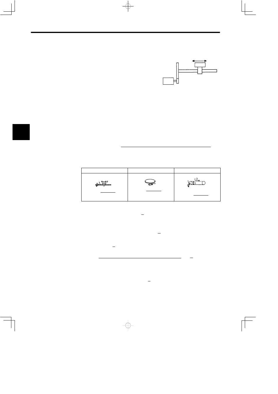
4. Determine the load travel distance per revolution of load shaft in reference units.
Load travel distance per revolution of load shaft (in reference units)
Load travel distance per revolution of load shaft (in unit of distance)
Reference unit
=
Example: When ball screw pitch is 5 mm and reference unit is 0.001 mm
5/0.001 = 5,000 (reference units)
Ball Screw
Disc Table
Belt & Pulley
Load shaft
1 revolution
P: Pitch
Reference unit
=
P
1 revolution
Reference unit
=
360°
Load shaft
D: Pulley diameter
Load shaft
1 revolution
Reference unit
=
π D
5. Determine the electronic gear ratio
B
A
.
If the load shaft makes “n” revolutions when the motor shaft makes “m” revolutions,
the gear ratio of motor shaft and load shaft is n
m.
Electronic gear ratio
B
A
Number of encoder pulses x 4
Travel distance per revolution of load shaft (in reference units)
=
× mn
NOTE
Make sure that the electronic gear ratio meets the following condition:
B
A
0.01 ≤ Electronic gear ratio
≤ 100
If the electronic gear ratio is outside this range, the SERVOPACK does not work prop-
erly. In this case, modify the load configuration or reference unit.
3
To move a table in 0.001 mm units
Reference unit: 0.001 mm
Determine the reference unit according to
machine specifications and positioning
accuracy.