Yaskawa SGDB User Manual
Page 130
APPLICATIONS OF Σ-SERIES PRODUCTS
3.6.2 Setting Servo Gain cont.
118
J
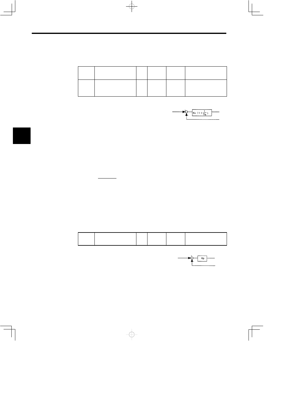
Setting Speed Loop
Set the following parameters related to speed loop as necessary.
Cn-04
LOOPHZ
Speed Loop Gain (Kv)
Unit:
Hz
Setting
Range: 1
to 2000
Factory
Setting:
80
For Speed/Torque
Control and Position
Control
Cn-05
PITIME
Speed Loop Integration
Time Constant (Ti)
Unit:
0.01
ms
Setting
Range:
200 to
51200
Factory
Setting:
2000
For Speed/Torque
Control and Position
Control
Cn-04 and Cn-05 are a speed loop gain and an in-
tegration time constant for the SERVOPACK,
respectively.
The higher the speed loop gain value or the small-
er the speed loop integration time constant value,
the higher the speed control response. There is,
however, a certain limit depending on machine
characteristics.
The unit of speed loop gain (Kv) is Hz, but this value is obtained when J
M
equals J
L
.
Therefore, the value must be converted using load J (= J
L
) as follows:
Kv value =
setting × 2
1 + J
L
∕J
L
These parameters are automatically set by the autotuning function.
The unit of speed loop integration time constant Cn-05 (Ti) can be changed to 0.01 ms.
J
Setting Position Loop
Set the following parameters related to position loop as necessary.
Cn-1A
POSGN
Position Loop Gain (Kp)
Unit:
1/s
Setting
Range: 1
to 200
Factory
Setting:
40
For Position Control
Only
This parameter is a position loop gain for the SER-
VOPACK.
Increasing the position loop gain value provides
position control with higher response and less
error. However, there is a certain limit depending
on machine characteristics. This gain is also valid
for zero clamp operation.
This parameter is automatically set by the autotuning function.
3
Speed
reference
Speed loop gain
Speed feedback
Note
If the Cn-28 constant is set, the
maximum allowable Cn-04 setting
may become smaller than 2000.
Position
reference
Position loop gain
Position feedback