Yaskawa SGDB User Manual
Page 169
3.8 Special Wiring
157
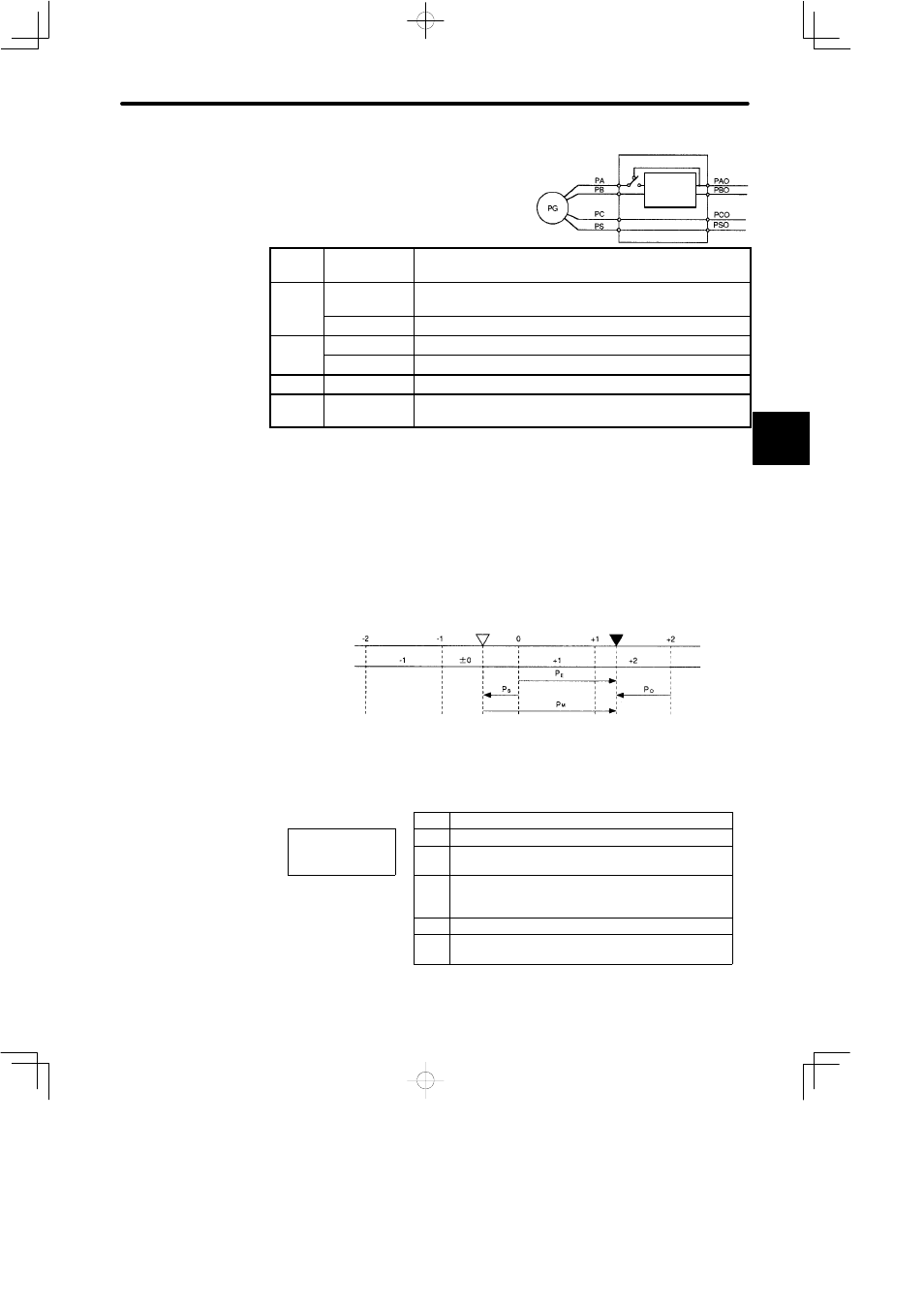
Outline of Absolute Signal
The absolute encoder outputs PAO, PBO,
PCO and PSO as shown on the right.
Signal
Name
Status
Contents
PAO
Initial state
Serial data
Initial incremental pulse
PAO
Normal state
Incremental pulse
PBO
Initial state
Initial incremental pulse
PBO
Normal state
Incremental pulse
PCO
Normal state
Home position pulse
PSO
Normal state
Rotation count serial data
(12-bit absolute encoder only)
Contents of Absolute Data
Serial Data:
Indicates how many turns the motor shaft has made from
the reference position (position specified at setup).
Initial Incremental Pulse:
Outputs pulses at the same pulse rate as when the motor
shaft rotates from the home position to the current posi-
tion at the maximum speed of 4,900 min
−1
.
Coordinate data
Reference position
(setup)
Current position
Value M
Absolute data P
M
can be determined using the following formula.
P
E
Current value read by encoder
P
E
= M ¢ R+P
O
M
Serial data (rotation count data)
P
E
= M ¢ R+P
O
P
M
= P
E
− P
S
P
O
Number of initial incremental pulses
(Normally, this is a negative value)
P
S
Number of initial incremental pulses read at setup
(Normally, this is a negative value stored and
controlled by a host controller.)
P
M
Current value required for the customer system
R
Number of pulses per encoder revolution
(pulse count after dividing, value of Cn-0A)
3
SERVOPACK
Frequency
dividing
circuit