2 troubleshooting problems with no alarm display – Yaskawa SGDB User Manual
Page 538
6.2 Troubleshooting
529
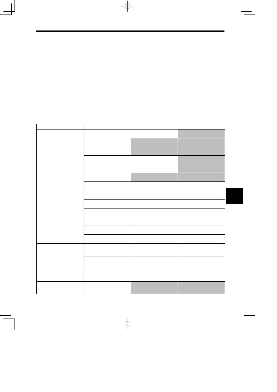
6.2.2 Troubleshooting Problems With No Alarm Display
Refer to the tables below to identify the cause of a problem which causes no alarm display
and take the remedy described.
Turn OFF the servo system power supply before commencing the shaded procedures.
Contact your Yaskawa representative if the problem cannot be solved by the described pro-
cedures.
Troubleshooting Table No Alarm Display
Symptom
Cause
Inspection
Remedy
Servomotor does not start
Power not connected
Check voltage between
power supply terminals.
Correct the power circuit.
Loose connection
Check terminals of
connectors (1CN, 2CN).
Tighten any loose parts.
Connector (1CN) external
wiring incorrect
Check connector (1CN)
external wiring
Refer to connection diagram
and correct wiring.
Servomotor or encoder
wiring disconnected.
Reconnect wiring
Overloaded
Run under no load.
Reduce load or replace with
larger capacity servomotor.
Speed/position references
not input
Check reference input pins.
Correctly input
speed/position references.
/S-ON is turned OFF
Cn-01 Bit 0 is 0.
Turn /S-ON input ON.
/P-CON input function
setting incorrect
Check parameter Cn-2B.
Refer to Section 3.2.1 and
set parameters to match
application.
Reference pulse mode
selection incorrect.
Refer to Section 3.2.2.
Select correct parameters
Cn-02 Bits 3, 4, 5.
Encoder type differs from
parameter setting.
Incremental or absolute
encoder?
Set parameters Cn-01 Bit E
to the encoder type used.
P-OT and N-OT inputs are
turned OFF.
(If Cn-01 Bits 2, 3 are 0)
Turn P-OT and N-OT input
signals ON.
CLR input is turned ON
Check status of error
counter clear input.
Turn CLR input OFF.
SEN input is turned OFF.
Absolute encoder used with
Cn-01 Bit 1 set to 0.
Turn SEN input ON.
Servomotor moves
instantaneously, then stops
Number of encoder pulses
differs from parameter
setting.
Set the parameter (Cn-11) to
match the number of
encoder pulses.
Servomotor or encoder
wiring incorrect.
Refer to Section 3.8.8 and
correct wiring.
Suddenly stops during
operation and will not restart
Alarm reset signal
(/ALM-RST) is turned ON
because an alarm occurred.
Remove cause of alarm.
Turn alarm reset signal
(/ALM-RST) from ON to
OFF.
Servomotor speed unstable
Wiring connection to motor
defective
Check connection of power
lead (U, V, and W phase)
and encoder connectors.
Tighten any loose terminals
or connectors.
6