2 main circuit wiring and power on sequence – Yaskawa SGDB User Manual
Page 46
BASIC USES OF Σ-SERIES PRODUCTS
2.3.2 Main Circuit Wiring and Power ON Sequence
34
2.3.2 Main Circuit Wiring and Power ON Sequence
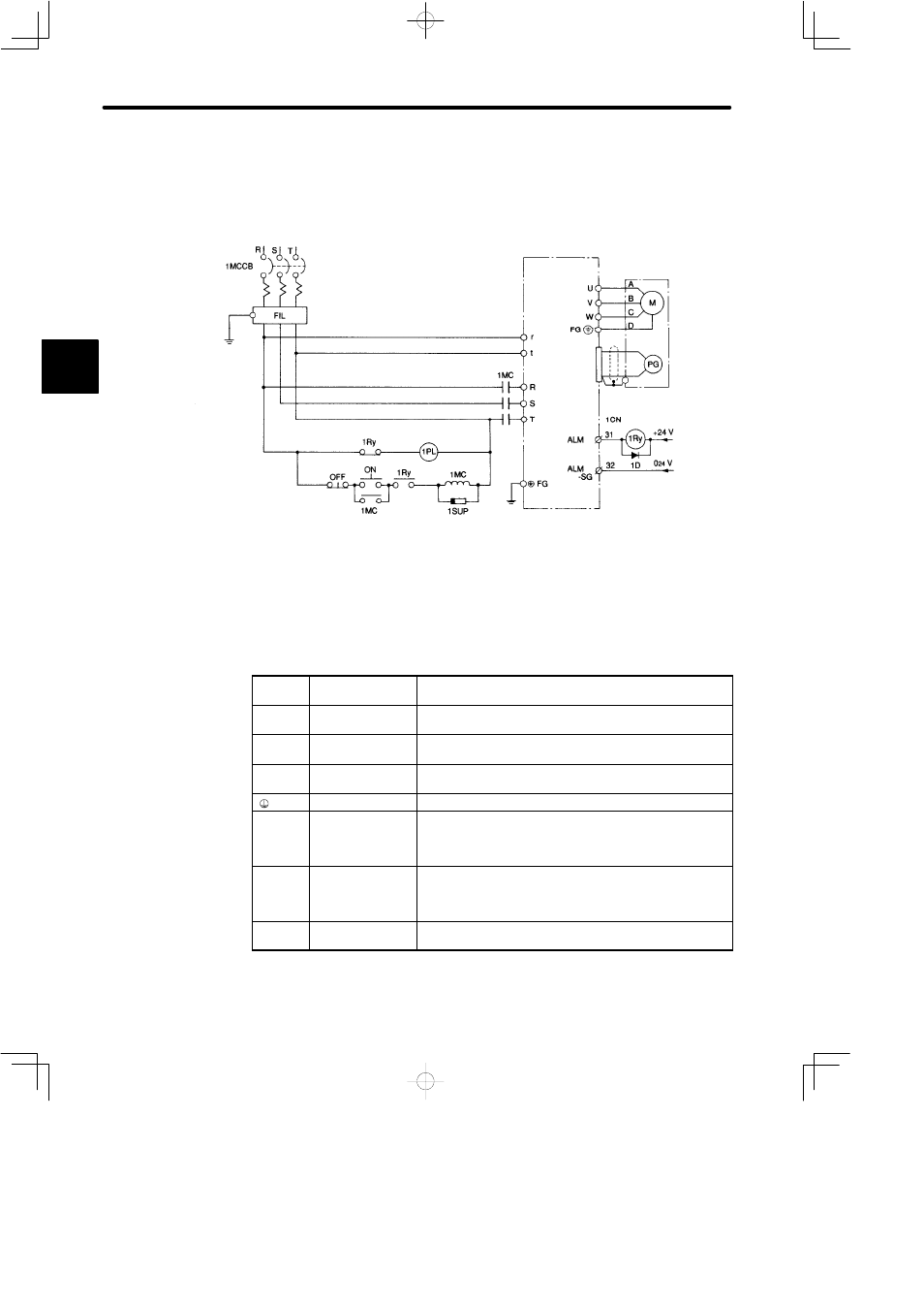
The following diagram shows a typical example of wiring the main circuit for Σ-Series
products:
1MCCB: Circuit breaker (for inverter type)
FIL:
Noise filter
1MC:
Contactor
1Ry:
Relay
1PL:
Lamp for display
1SUP:
Surge suppressor
1D:
Flywheel diode
(Alarm lamp)
Main circuit
power
Main circuit power
Three-phase 200 to 230 VAC
(50/60 Hz)
+ 10%
–15%
SERVOPACK
SGDB-jjADj
The following table shows the name and description of each main circuit terminal:
Terminal
Symbol
Name
Description
R, S, T
Main power input
terminals
Three-phase 200 to 230 VAC
, 50/60Hz
+ 10
–15
%
U, V, W
Motor connection
terminal
Used to connect motor
r, t
Control power
input terminals
Single phase 200 to 230 VAC
, 50/60Hz
+ 10
–15
%
×2
Ground terminal
Connected to earth. (For power ground and motor ground).
P, B
Regenerative
resistor unit
connection
terminal
Normally, external connection is not required.
P1, B
Regenerative
resistor unit
connection
terminal
Terminal used to connect regenerative resistor for
SERVOPACK with power capacity more than 6 kW.
N
Main circuit minus
side terminal.
Normally, external connection is not required.
Note
P1 terminal is not available for SERVOPACK with power capacity less than 5 kW.
2