12 magnetic contactor, Servo selection and data sheets, Hi-15j hi-18j – Yaskawa SGDB User Manual
Page 498: Hi-20j

SERVO SELECTION AND DATA SHEETS
5.6.12 Magnetic Contactor
488
5.6.12 Magnetic Contactor
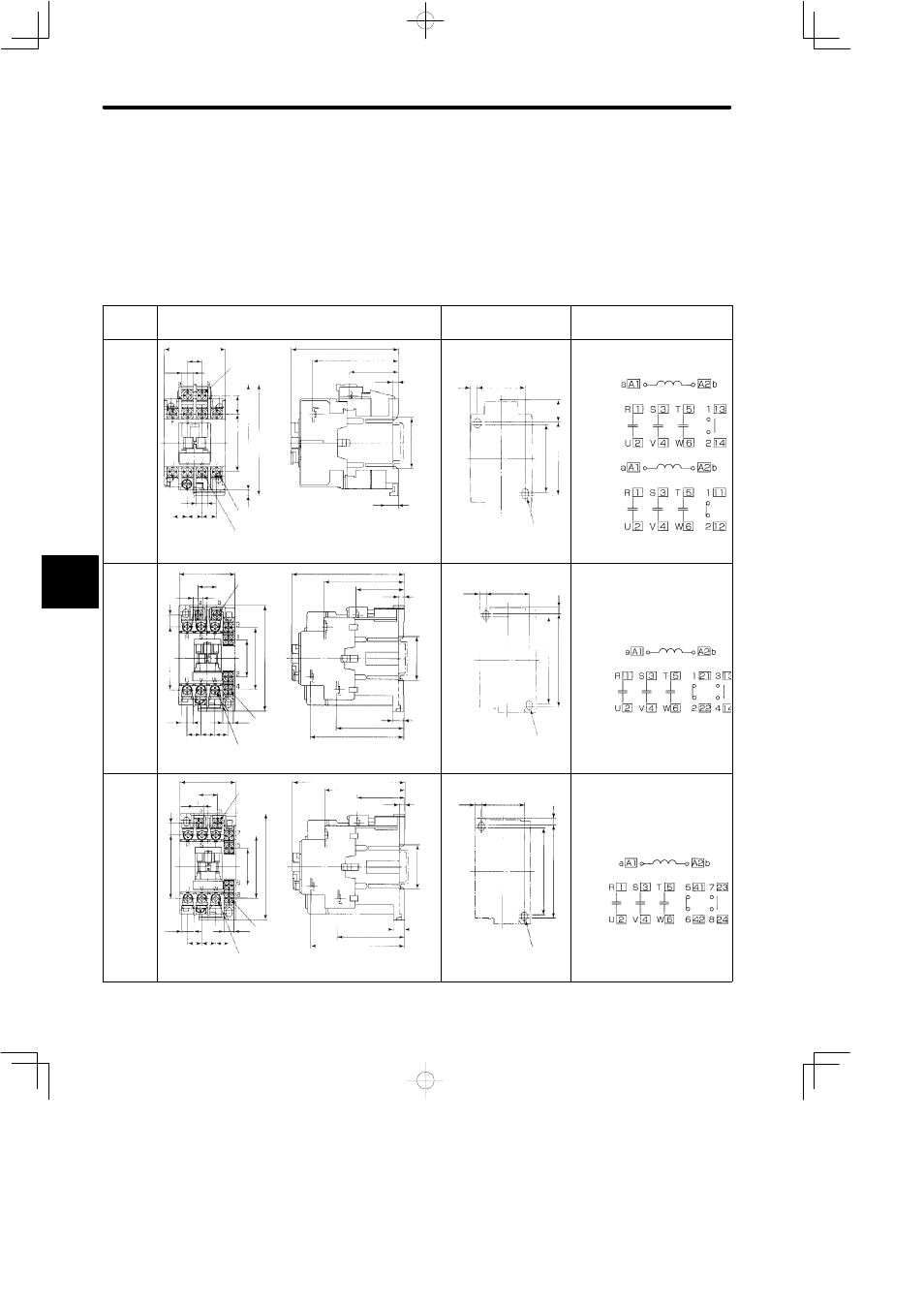
A magnetic connector turns ON and OFF the servo. Be sure to attach a surge suppressor
to the excitation coil of the magnetic contactor.
Select a magnetic contactor based on the current capacity of the SERVOPACK. For mul-
tiple servo systems, select a contactor based on total current capacity.
Following table shows external dimensions and terminal symbols for the magnetic con-
tactor.
Model
External Dimensions [mm (in)]
Mounting Hole
Dimensions [mm (in)]
Terminal Symbols
HI-11J
HI-14J
Coil terminal
M3.5
Auxiliary contact terminal M3.5
Main contact terminal M3.5
44 (1.73)
10.1 (0.40)
8.2
(0.32)
13
(0.51)
41
(1.61)
74.5
(2.93)
78.5
(3.09)
8.2
(0.32)
10.4
(0.41)
10.4
(0.41)
10.4
(0.41)
76 (2.99)
61 (2.40)
34.5 (1.36)
4.5 (0.18)
35
(1.38)
9 (0.35)
4
(0.16)
Approx. mass: 0.25 kg (0.551 lb)
2×M4 mounting
holes
5 (0.20)
34 (1.34)
15.5 (0.61)
48
(1.89)
52
(2.05)
Auxiliary NO contact
Auxiliary NC contact
HI-15J
HI-18J
Coil terminal
M3.5
Auxiliary contact
terminal M3.5
Main contact terminal M4
45.5 (1.79)
15.3 (0.60)
8.2
(0.32)
9.6
(0.38)
51
(2.01)
9.6
(0.38)
11.3
(0.44)
11.3
(0.44)
10.8
(0.43)
8.2
(0.32)
29
(1.14)
50
(1.97)
85
(3.35)
91 (3.58)
65 (2.56)
39 (1.54)
4.5 (0.18)
35
(1.38)
9 (0.35)
54 (2.13)
76 (2.99)
Approx. mass: 0.38 kg (0.838 lb)
2×M4 mounting
holes
5.2 (0.20)
35 (1.38)
5
(0.20)
70
(2.76)
75
(2.95)
Auxiliary NO contact/
Auxiliary NC contact
HI-20J
Coil terminal
M3.5
Auxiliary contact
terminal M3.5
Main contact terminal M4
45.5 (1.79)
15.3 (0.60)
8.2
(0.32)
9.6
(0.38)
51
(2.01)
9.6
(0.38)
11.3
(0.44)
11.3
(0.44)
10.8
(0.43)
8.2
(0.32)
29
(1.14)
50
(1.97)
85
(3.35)
91 (3.58)
65 (2.56)
39 (1.54)
4.5 (0.18)
35
(1.38)
9 (0.35)
54 (2.13)
76 (2.99)
Approx. mass: 0.38 kg (0.838 lb)
2×M4 mounting
holes
5.2 (0.20)
35 (1.38)
5
(0.20)
70
(2.76)
75
(2.95)
Auxiliary NO contact/
Auxiliary NC contact
5
