7 using servo ready output signal, Output → /s-rdy – Yaskawa SGDB User Manual
Page 152
APPLICATIONS OF Σ-SERIES PRODUCTS
3.7.7 Using Servo Ready Output Signal
140
3.7.7 Using Servo Ready Output Signal
This section describes how to wire and use photocoupler output signal /S-RDY (servo
ready).
“Servo ready” means that the SERVOPACK is not in servo alarm state when the main
circuit is turned ON. For absolute encoder specifications, “servo ready” means that, in
addition to the above, the SEN signal is at high level and the absolute encoder is also in
ready state.
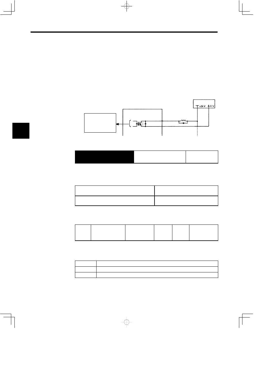
SGDB SERVOPACK
I/O power
supply
Photocoupler Output
Per output:
Maximum operation
voltage: 30 VDC
Maximum output
current: 50 mADC
/S-RDY+
/S-RDY−
Output → /S-RDY
Servo Ready Output
For Speed/Torque
Control and
Position Control
This signal indicates that the SERVOPACK is ready to receive servo ON signals.
ON
status:
Circuit is closed or signal is at low level. Servo ready state
OFF
status:
Circuit is open or signal is at high level.
Not in servo ready state
Use the following parameter to specify the pin to which the /S-RDY signal is to be output.
Cn-2D
OUTSEL Output
signal
selection
Setting Range:
110 to 666
Factory
Setting:
210
For
Speed/Torque
Control and
Position Control
This parameter is used to specify a function signal as the 1CN output signal.
1s place
Select the 1CN-25 and 1CN-26 (/COIN, /V-CMP) functions.
10s place
Select the 1CN-27 and 1CN-28 (/TGON) functions.
100s place
Select the 1CN-29 and 1CN-30 (/S-RDY) functions.
Example: /S-RDY is output to 1CN-29 and 1CN-30.
Cn-2D=2jj
3