Yaskawa SGDB User Manual
Page 141
3.7 Forming a Protective Sequence
129
J
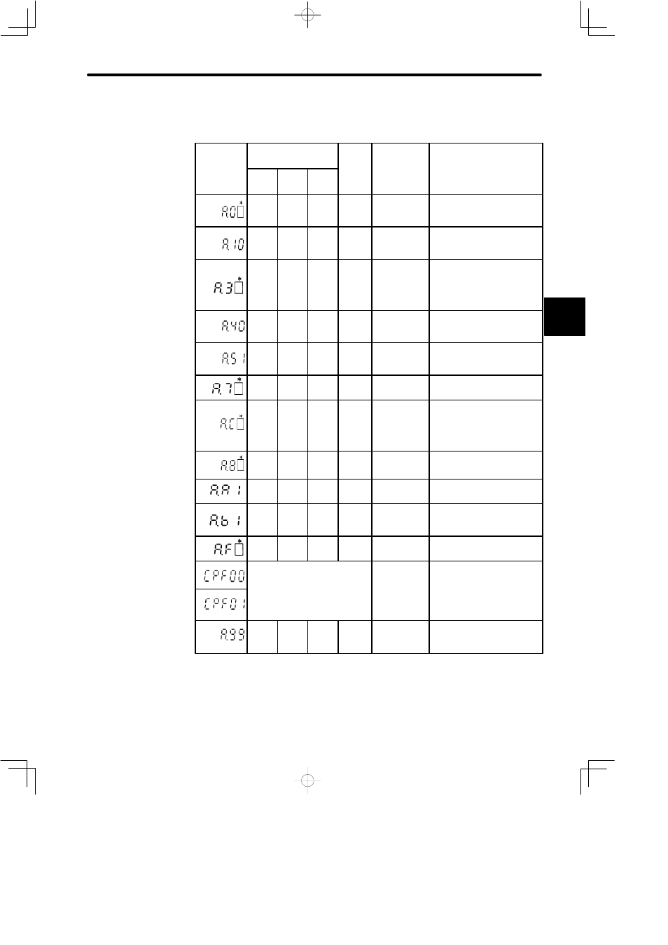
Relationship between Alarm Display and Alarm Code Output
Alarm Display and Alarm Code Output:
Alarm
Alarm Code Output
Servo
Alarm
(ALM)
Alarm Type
Alarm Description
Alarm
Display
ALO1 ALO2 ALO3
(ALM)
Out-
put
Alarm Type
Alarm Description
¢
¢
¢
¢
User
constant
error
An absolute encoder error
occurred or parameter is
faulty.
○
¢
¢
¢
Overcurrent
Overcurrent flowed thorough
the main circuit.
SERVOPACK overheated.
○
○
¢
¢
Regenerative
error.
Position error
pulse
overflow
Regenerative circuit is faulty.
The number of pulses in er-
ror counter has exceeded
the preset value.
¢
¢
○
¢
Main power
voltage error
Main circuit DC voltage has
exceeded approximately
420 V.
○
¢
○
¢
Overspeed
Motor speed has exceeded
the maximum allowable
speed.
○
○
○
¢
Overload
Motor and SERVOPACK are
overloaded.
○
¢
○
¢
Overrun
Disconnec-
tion of PG
signal line
Overrun occurred due to mo-
tor or encoder signal wiring
faults.
Encoder signal line is dis-
connected.
¢
¢
¢
¢
Absolute en-
coder error
Absolute encoder is faulty.
○
○
○
¢
Heatsink
overheat
SERVOPACK heat sink
overheated.
¢
¢
¢
¢
Reference
input read er-
ror
Reference input failed to be
detected.
¢
○
¢
¢
Power line
open phase
One phase is missing from
main circuit power supply.
U d fi d
Digital Oper-
ator trans-
mission error
Communication error oc-
curred between Digital Oper-
ator and SERVOPACK.
Undefined
mission error ator and SERVOPACK.
¢
¢
¢
○
No error
○ : Output transistor is ON
¢
: Output transistor is OFF (Alarm state)
* : Displays an alarm category number.
For details, refer to Appendix D List of Alarm Displays.
3