12 using the analog monitor, Output → trq-m 1cn-16, Output → vtg-m 1cn-17 – Yaskawa SGDB User Manual
Page 111
3.2 Setting Parameters According to Host Controller
99
3.2.12 Using the Analog Monitor
The following two analog voltage monitor signals are output.
Output → TRQ-M 1CN-16
Torque Monitor
For Speed/Torque Control
and Position Control
Output → VTG-M 1CN-17
Speed Monitor
For Speed/Torque Control
and Position Control
The following memory switch is used to modify the signal specifications.
Bit 6
TRQ-M Specifications
Factory
Setting: 0
Cn-02
Bit 7
VTG-M Specifications
Factory
Setting: 0
Bit E
Error Pulse Monitor Level
Changeover
Factory
Setting: 0
TRQ-M
Cn-02 Bit 6
Control Mode
Specifications
0
−−−−
Torque monitor
(2V/100% torque)
1
Torque control
(Undefined)
Speed control
Speed reference monitor*
Position control
Reference pulse speed
monitor*
VTG-M
Cn-02 Bit 7
Control Mode
Specifications
0
−−−−
Speed monitor*
1
Speed/torque
(Undefined)
1
Speed/torque
control
(Undefined)
Position control
Error pulse
monitor
Cn-02 bit E = 0: 0 .05 V/1
reference unit
monitor
reference unit
Cn-02 bit E = 1: 0.05 V/100
reference units
* For the SGMG and SGMD series, the unit is
2V/
1000 min
−1
.
For the SGMS, SGM and SGMP series, the unit is
1V/
1000 min
−1
.
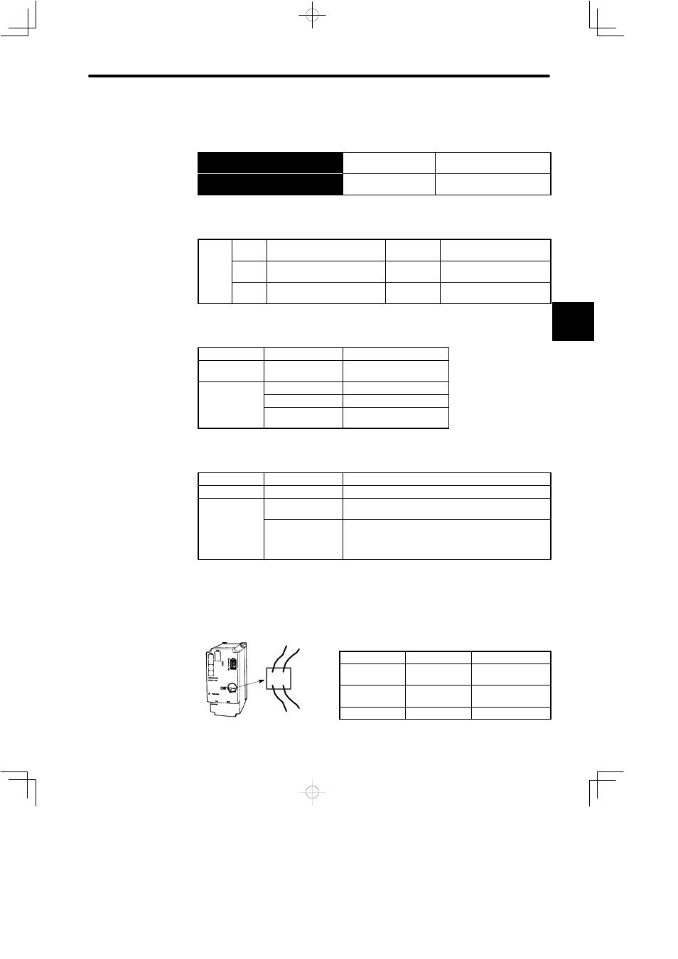
Analog monitor can also be available with exclusive-use cable (type: DE9404559) from
5CN connector.
Cable Color
Signal Name
Contents
Red
VTG-M
Speed/error pulse
monitor
White
TRQ-M
Torque/speed
reference monitor
Black (x2)
GND
Grounding
3
White
Red
Black
Black
5CN