Yaskawa SGDB User Manual
Page 364

USING THE DIGITAL OPERATOR
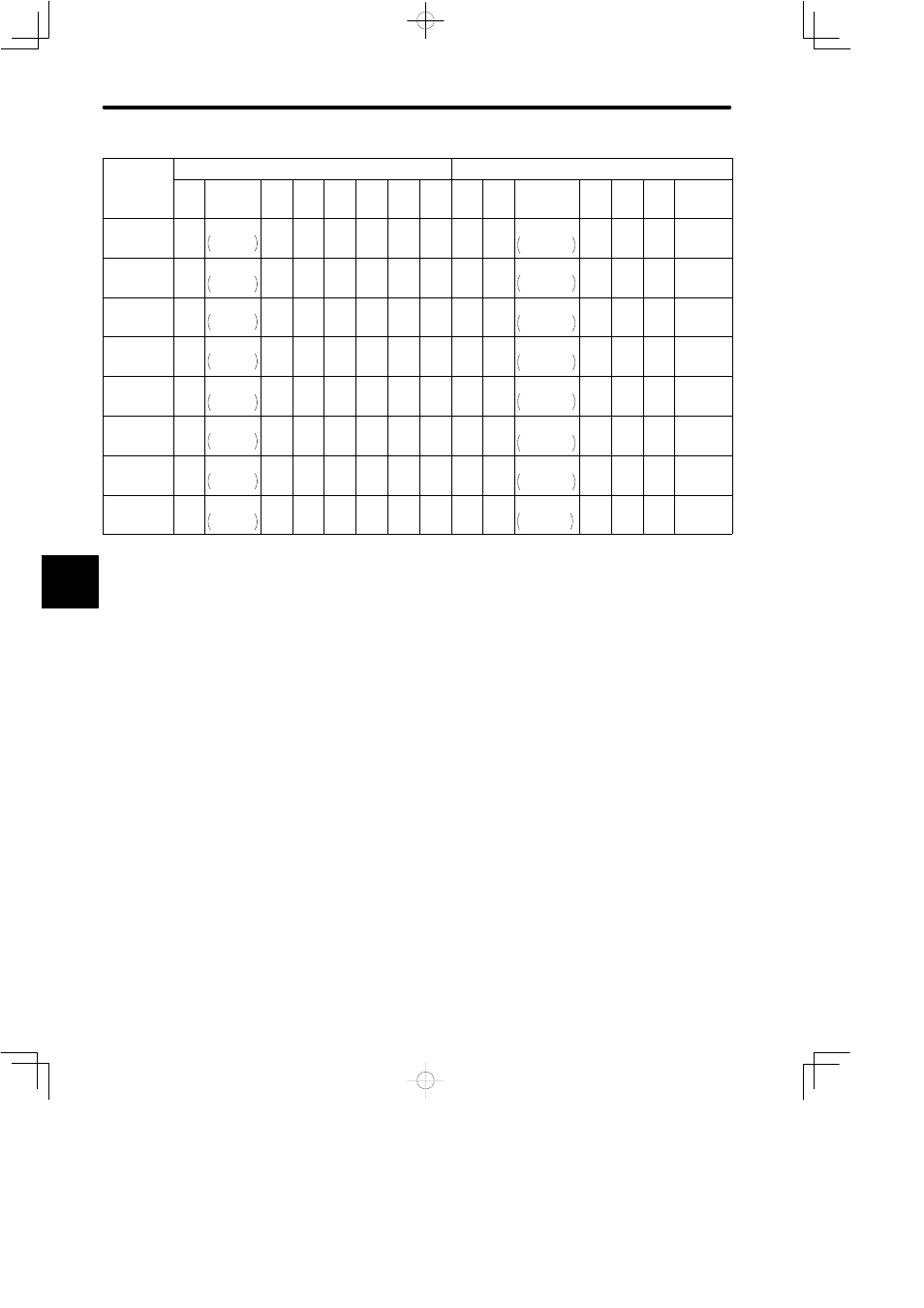
5.4.1 Servomotor Dimensional Drawings cont.
354
in mm (inches)
Motor type
Flange dimensions
Shaft end dimensions
SGMG-
LA
LB
LC
LE
LG
LR
N
LZ
Q
QK
S
T
U
W
V
20A2BT7R
310
(12.2)
10.6
+0.0054
+0.0022
270
+0.137
+0.056
340
(13.4)
4
(0.16)
20
(0.79)
89
(3.50)
6
(0.24)
11
(0.43)
90
(3.54)
80
(3.15)
φ60
0
−0.019
φ2.36
0
−0.0007
11
(0.43)
7
(0.28)
18
(0.71)
M10 screw,
depth 18
30A2BTCR
310
(12.2)
10.6
+0.0054
+0.0022
270
+0.137
+0.056
340
(13.4)
4
(0.16)
20
(0.79)
89
(3.50)
6
(0.24)
11
(0.43)
90
(3.54)
80
(3.15)
φ60
0
−0.019
φ2.36
0
−0.0007
11
(0.43)
7
(0.28)
18
(0.71)
M10 screw,
depth 18
30A2BT7R
360
(14.2)
12.4
+0.0059
+0.0024
316
+0.151
+0.062
400
(15.7)
5
(0.20)
22
(0.87)
94
(3.70)
8
(0.31)
14
(0.55)
90
(3.54)
80
(3.15)
φ70
0
−0.016
φ2.76
0
−0.0006
12
(0.47)
7.5
(0.30)
20
(0.79)
M12 screw,
depth 24
44A2BTCR
360
(14.2)
12.4
+0.0059
+0.0024
316
+0.151
+0.062
400
(15.7)
5
(0.20)
22
(0.87)
94
(3.70)
8
(0.31)
14
(0.55)
90
(3.54)
80
(3.15)
φ70
0
−0.016
φ2.76
0
−0.0006
12
(0.47)
7.5
(0.30)
20
(0.79)
M12 screw,
depth 24
44A2BT7R
360
(14.2)
12.4
+0.0059
+0.0024
316
+0.151
+0.062
400
(15.7)
5
(0.20)
22
(0.87)
94
(3.70)
8
(0.31)
14
(0.55)
90
(3.54)
80
(3.15)
φ70
0
−0.016
φ2.76
0
−0.0006
12
(0.47)
7.5
(0.30)
20
(0.79)
M12 screw,
depth 24
60A2BTBR
310
(12.2)
10.6
+0.0054
+0.0022
270
+0.137
+0.056
340
(13.4)
4
(0.16)
20
(0.79)
89
(3.50)
6
(0.24)
11
(0.43)
90
(3.54)
80
(3.15)
φ60
0
−0.019
φ2.36
0
−0.0007
11
(0.43)
5
(0.20)
18
(0.71)
M10 screw,
depth 18
60A2BTCR
360
(14.2)
12.4
+0.0059
+0.0024
316
+0.151
+0.062
400
(15.7)
5
(0.20)
22
(0.87)
94
(3.70)
8
(0.31)
14
(0.55)
90
(3.54)
80
(3.15)
φ70
0
−0.016
φ2.76
0
−0.0006
12
(0.47)
7.5
(0.30)
20
(0.79)
M12 screw,
depth 24
60A2BT7R
390
(15.4)
13.58
+0.0059
+0.0024
345
+0.151
+0.062
430
(16.9)
5
(0.20)
22
(0.87)
110
(4.33)
8
(0.31)
18
(0.71)
110
(4.33)
100
(3.94)
φ80
0
−0.016
φ3.15
0
−0.0006
14
(0.55)
9
(0.35)
22
(0.87)
M12 screw,
depth 24
5
